This thread has been locked.

If you have a related question, please click the "Ask a related question" button in the top right corner. The newly created question will be automatically linked to this question.

UCC28780: UCC28780EVM-021 doesn't start

Part Number: UCC28780

Hello,

I am using UCC28780EVM-021. It was working properly but suddenly it is not working. I have not changed any components and the pins HVG, CS, Rtz and Rdm are not short or open circuited. I don't know the problem. I am attaching the waveforms. Please help. RUN and PWML not working.

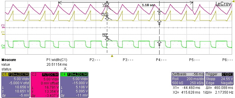
1.  Every ninth discharge time is smaller than first eight discharge times.

In the smaller discharge time, we can see two slopes. Can you give me the reason behind it? The time measured between the first VDDon point after the smaller discharge time, to the point (slope change point) in the next small discharge time is 1.18sec. It is marked in the waveform.

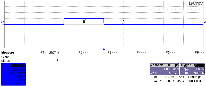
2. Run pin has a small pulse on every cycle when VDD reaches VDDon.

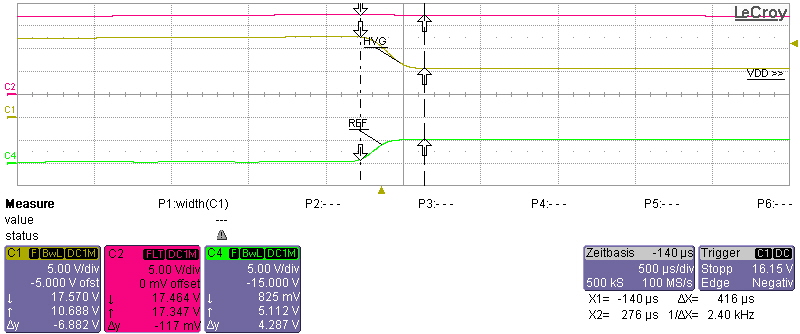
3. This shows the time taken by HVG pin to settle down to 11V.

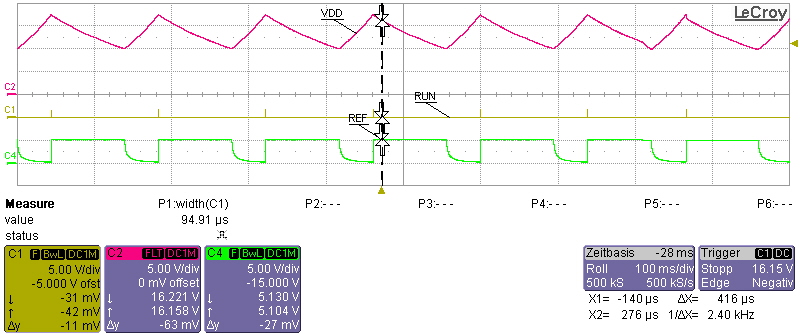
I have also made circuit using UCC28780. As I am waiting for the new transformer, till that time, I am using my old transformer with high primary inductance (695uH). I have calculated Rdm and Rtz according to the 695uH inductance. I am facing almost the same problem with this circuit too. I am attaching the wave forms what I get on my circuit. RUN and PWML not working.

1. Every third discharge time is smaller than first and second discharge times. The time measured between the first VDDon point after the smaller discharge time, to the point (slope change point) in the next small discharge time is 1.21sec. It is marked in the waveform.

2. This shows the time taken by HVG pin to settle to 11V.

Please suggest me some steps to troubleshoot.

In datasheet section "7.4.10 System Fault Protections" and "7.4.11 Pin Open/Short Protections" various faults have been listed. Can you tell me which faults are being checked during "7.4.8 Startup Sequence"??

  • Hello Mike,

    As you said, there will be four PWML pulses to check for a fault, but I have checked that there is not a single pulse coming.

    As per datasheet section "7.4.10 System fault protections", It senses CS voltage, VS voltage and VS current for faults. But as there is no PWML, I don't think I will get any signals on CS or VS pin. I have checked the voltage on CS and VS pins as well. It is 0V.

    I want to ask when the device will look for Over temperature Fault(OTP) on NTC pin? after soft-start or before? because I am getting one 150mV pulse on NTC pin when VDD equals VDDon.
  • Hello Nisarg,

    Trigger on the PWML pin there should be pulses to sample for fault. You just might not be able to see them at them due to the time base you have set your scope for.

    These pulse will occur after VDD has reached VDD(on).
    I would not think this is not an over temperature issue, because the controller is not delivering any power. However, the over temperature fault is active in the soft start region.

    Regards,

    Mike
  • Hello Mike,

    Yes you were right. I am getting pulse on PWML when VDD equals VDDON.

    In the following figure (Fig.1), I have marked time 1.18sec. At the beginning of that time, when VDD is VDDon, I am getting only one PWM pulse (Fig.2) of 2us width and 5V amplitude.

    Fig.1

    Fig. 2

    But when I check the output of the driver at LO pin, I get following (Fig.3) pulse. 2us width but 2V amplitude. What could be the reason?

    Fig.3

  • Hello Nisarg,

    If you increase the time base you should see 3 pulses that are sampling for a fault. You just need to figure out which one.

    There was a PDF explaining how to check for the fault with suggestions in these e2e posts.

    Regards,

    Mike
  • Hi,

    Can you please send that PDF which explains how to check for faults?
    I am not able to find it in e2e posts.
    Thanks!
  • Hello Nisarg,

    I believe the PDF can be found at the following link.

    e2e.ti.com/.../Hello-Nisarg.pdf

    Regards,

    Mike