This thread has been locked.

If you have a related question, please click the "Ask a related question" button in the top right corner. The newly created question will be automatically linked to this question.

TLV431: Unclear value reference current

Part Number: TLV431
Other Parts Discussed in Thread: TL431

Hi all,

I'm doing a theoretical voltage accuracy analysis on TLV431 Low-Voltage Adjustable Precision Shunt Regulator with Vka > Vref and I found some specifications in the datasheet, which don't make sense to me.  Basically I try to find a  minimum reference current for the TLV431 to work fine.

My circuit looks similar to fig. 23 given in the datasheet:


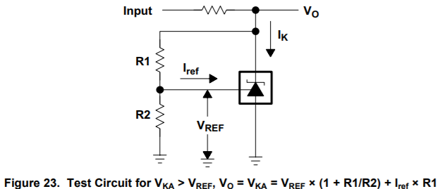
The datasheet can be found at: www.ti.com/.../slvs139x.pdf

On page 4 under 6.1 (Absolute Maximum Ratings) it says that the reference current (Iref) has to be between -0.05mA and 3mA. 

The following page (5) indicates ,under specified test conditions, at 6.5 (Electrical Characteristics for TLV431) 
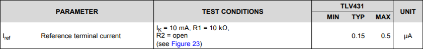
which is fine.

Then, on page 17 in section 8.3 (Feature Description) it is written, that the reference pin needs at least 0.5µA to work proper.

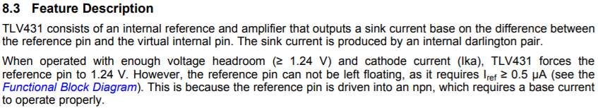
Now to my question: Does this mean, that the minimum working current is 0.5µA as stated in 8.3 and the values for the test conditions do not apply to my circuit (Vka > Vref)? Or can the device work with reference currents below 0.5 µA in my circuit as well?

Furthermore I'm getting confused with the negative minimum current as shown in 6.1. If there would be a negative current, my reference voltage would get falsified since the current generates an voltage over R2. Anyway a negative current out of an npn base doesn't make sense to me under this circumstances and would cause the device to not work as desired.

Any help on this would be appreciated.

PS: Throughout my investigations I noticed the same thing for the TL431 device, which works in a similar way with different reference voltage.

  • Hi Robert,

    Thank you for bringing this to our attention. If you are building figure 23, then I would just use the Iref in the EC table.
    A way of explaining this is the TLV431 can work in open and closed loop configurations.
    In open loop the Iref should be limited to an ABS max of 3mA
    In closed loop the Iref will can only be a maximum of 0.5uA at 25C
    Most of the EC table in TLV431 is for closed loop configuration. If you are sizing the resistors based on the current consumed by Iref, I would use the maximum value of 0.5uA in closed loop.

    Section 8.3 is a bit misleading and I will try to revise it in the next datasheet revision.

    The negative current in the ABS max is if you are pulling current out of the pin as this can happen in some latch up or undesired situations

    -Marcoo
  • Hi Marcoo,

    Many thanks for your explanation, that clarifies a lot.

    Is there a minimum Iref for closed loop usage?
  • Hi Robert,

    The device itself will regulate it self to use the minimum required Iref which is the EC table value. In the TLV431 it will be 0.15uA typical with 0.5uA max. I would design using the max for robustness. Keep n mind these values are for 25C and if you want to include temperature correction then I would add the additional value of Iref(dev) so a TLV431C would be 0.5uA at 25C to 0.8uA across temp.

    -Marcoo