This thread has been locked.

If you have a related question, please click the "Ask a related question" button in the top right corner. The newly created question will be automatically linked to this question.

TLV431B-Q1: Stability Boundary Conditions Output Capacitance

Part Number: TLV431B-Q1
Other Parts Discussed in Thread: TLV431A, , TLV431

Hello,

I am attempted to use the TLV431B-Q1 as a 3.3V shunt regulator in a design. The expected load will vary in capacitance (worst case 10uF) so I have a question regarding Figure 18 in the datasheet. Particularly, do the same stability boundary conditions apply? The figure is labelled for the TLV431A only. Please let me know if these conditions also apply to the TLV431B-Q1.

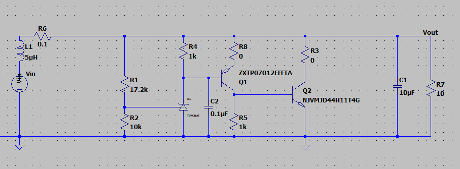
I've attached a picture of my circuit here. For some reason, I see a stable output when I place a 0.1uF cap from the TLV431's anode to cathode. This seemingly violates the stability boundary conditions of the circuit. (it's stable even when the 10uF cap is removed too) Please let me know about both the datasheet and this apparent contradiction.

Thank you!

  • Hi Sean,

    The stability region of the TLV431 graph applies mainly for the closed loop configuration without the transistors. An example of this is the testing diagram that was used for that section. Deviations from this diagram can change the stability region. What you are seeing now is a shift in the stability region due to your configuration. From my experience, adding transistors typically increase the unstable regions which is why C1 at 10uF with no C2 can be unstable. C1 is the proper load capacitor that should be looked at for stability. By adding C2 you added a pole which can change the response time of the circuit and thus stabilizing the circuit with C1.

    -Marcoo
  • Thanks! This helped clarify things.