This thread has been locked.

If you have a related question, please click the "Ask a related question" button in the top right corner. The newly created question will be automatically linked to this question.

Generating a square wave of 40Vdc 125A 20kHz output?

Other Parts Discussed in Thread: LM5104

Hi

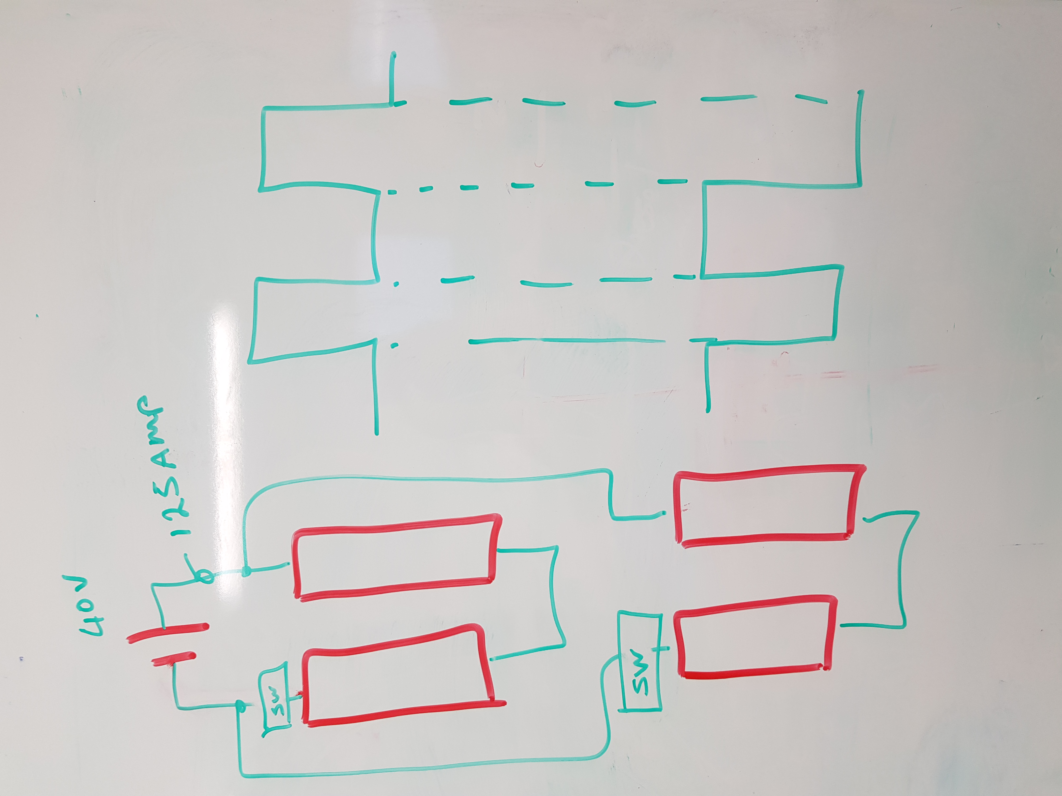
I need to use a power supply with square wave 40Vdc, adjustable current from 10-125A and adjustable frequency of 2 to 20KHz.

Is this achievable? If yes how? New to this and need some direction 

Thank you in advance

Steven

  • Hello Steven,
    Thank you for posting.
    I will need to do some research on this.
    I will reply by end of day Friday.

    Thank you for your patience.
  • Steven, what is the input voltage range of your design?
    Power supply specifications need a Vin as well as Vout Iout.

    Do you have slew rate specifications on the square wave edges?

    What kind of load will you be driving?
    A reactive load (capacitive or inductive) adds levels of complexity.

    Any other details of what you need will help the search.
    Thank you.
  • Hi Ed

    We have a Sorensen power supply. It output 40Vdc and 125A. Unfortunately ~20kHz square wave is the critical component for this test we are doing.

    This power supply cannot achieve that, but we can use it as Vin? if not 3 Phase Line-Line: 200VAC-240VAC is preferred.

    No specification on the slew rate at this stage. I assume the faster the better but not critical. 

    load is  a resistive load. 

    The test need to run multiple loads. Saving some cost we are hoping to use one power supply for two set of loads by switching the square wave out of phase. Not sure if this is achievable.

    Thank you

    Steven

  • Hello Steven,

    I was thinking along the same lines as your drawing, at first.
    Your mosfets are shown in a bridge configuration which would allow the output to be +-40V switched.

    But do you need -40V?
    Creating a +-40V would require driving 4 mosfets as you show.

    A simple switch between the power source and the load would modulate the power to the load.
    This would produce a 0 to +40V square wave output.

    This is a picture from a TI app note; 
    Cut-Off Switch in High-Current Motor-Drive Applications
    http://www.ti.com/lit/an/slva991a/slva991a.pdf


    Your power source may have enough capacitance at its output to keep the turn on spikes low enough.
    But you could add some more capacitance if needed, before the switch, so the caps source the current spikes into the load.

    TI has power N Fets up to 100V VDS
    http://www.ti.com/power-management/mosfets/n-channel-transistors/products.html#p267=59;100

    This mosfet is one to consider.
    www.ti.com/.../csd19532ktt
    100 V, 4.6 mΩ, D 2PAK (TO-263) NexFET™

    I would suggest 3 or 4 in parallel to keep losses, and heat, low.


    The NPN PNP gate arrangement would be lowest cost.
    You will need to experiment with how much current you drive the gate with in order to get the waveform dynamics you want.

    The wires connecting the load and switch, both positive and ground, have inductance which will induce voltage spikes as the switch.
    V=Ldi/dt.
    You should consider some clamps and/or snubbers in the design to control these spikes.
    Otherwise they could damage the mosfets by exceeding their VDS rating.

    I welcome your thoughts.

  • Hello Steven,

    Producing a 40V 125 square wave conversion is the same thing as creating a high current DC DC converter.
    The square wave you want to  make is what would be input to the inductor of a buck converter.
    The only way to reduce the current to a resistive load is to reduce the average voltage at the load.

    I=V/R

    If you want a 10 amp pulse into a fixed R, the V applied must be controlled.
    To  maintain a square wave pulse of current, the Vin to the switches must be controlled.

    A circuit like the below could switch your power source into the load.
    You can adjust Vin by adjusting Vset of your Sorenson supply.

    The IN of the LM5104 would be the frequency and duty cycle that you want to apply to the load.
    To adjust current, you adjust Vout of the Sorenson, which is Vin to this converter.

    Duty cycle control allows you to vary the average current.
    If you want a true 50% duty square wave you can.

    And you are switching a LOT of current to make a square wave.
    The mosfets in the above diagram would need to be large.
    When you look at designs similar to your Vin and Iout, they are all multiphase, many dcdc in parallel.

    You are looking at several mosfets in parallel for each location, and perhaps multiple stages just to control the heat.

    These are things to consider.