This thread has been locked.

If you have a related question, please click the "Ask a related question" button in the top right corner. The newly created question will be automatically linked to this question.

LM5064: Device shutdown during other card plugin

Part Number: LM5064
Other Parts Discussed in Thread: LM5050-2,

Hi Team,

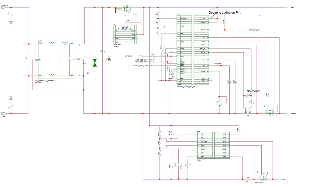
Customer is using  device in multiple boards and these boards are connected to system back plane. LM5064 hot swap controller is used for 48V feed. Connection flow is Backplane Connector---> EMI Filter (Murata- BNX023-01L)--->LM5050-2 Based Active Oring FET controller--->LM5064 Hotswap controller

LM5064 turns off the output voltage and restarts when another card of the same type is inserted to back plane. Fault logs indicates IIN_OC/PFET_OP_FAULT bit in the DIAGNOSTIC_WORD (E1h) register.

We monitored over current and power limit but could not see any evidence of input over current or power limit being crossed on the feed from back plane. Further analysis done with few other tests, observed that if the EMI filter is removed, IIN_OC FAULT is not reported. We tested and observed for UV/OV did not see any alarms corresponding to UVLO and OVLO during failure.

Please help with your quick inputs to analyse and rectify this issue.

Regards, Shinu Mathew.

  • Hi Shinu,

    Can you please share the schematic. Can you also go through the app note www.ti.com/.../slva703.pdf which highlight the false-shutdown during transients from adjacent card insertion/removal and faults on adjacent cards.

    Best Regards,
    Rakesh
  • Hi Rakesh,

    Thanks for the reply, will get back with schematics.

    Regards, Shinu Mathew
  • Hi Rakesh,

    Please find the attached schematics.

    R9 and R1290 are not mounted on board. Decap is mounted between the VCC pin and VEE pin.


    Below suggestions from the document are tried in customer board.

    -        Addition of filter on Sense Pin Mounted R9 and R10 with 10nF and 10Ohm resistor combination but still issue is present.

    -        Increasing CB/CL ratio to 3.9 while keeping CL=50mV does not solve the problem.

    -        Increasing the power limit to 320W did not solve the issue.

    -        Keeping Resistor divider R9 and R10 as 10Ohm does not solve the issue.

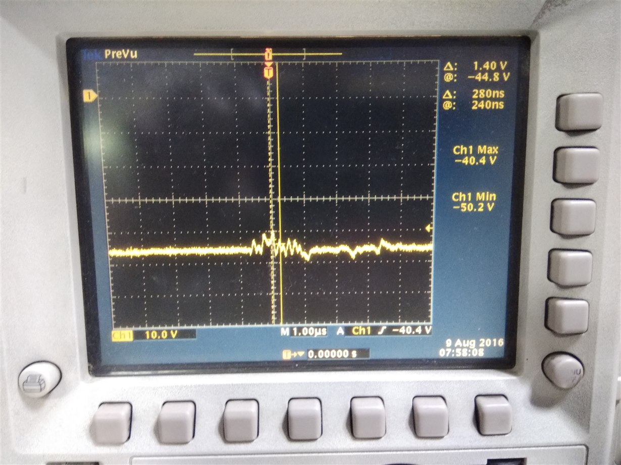
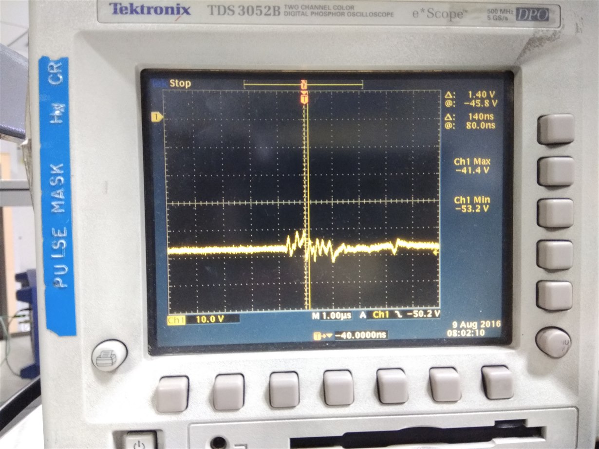
     Captured the waveform on UVLO and OVLO pins. We could observe only very short duration spikes which is far less than the Fault timer limits. See the attached waveforms (captured on UVLO and OVLO pins). Problem is seen when there is no Load also. i.e when 48V to 12V power modules turned off also.

    Regards, Shinu Mathew.

  • Hi Shinu,

    Thanks for the more details.
    We need to probe further test nodes to understand the reason. As you already mentioned that without filter there is no issue of shutdown. The input filter adds inductance and creates oscillations like the one explained in the app note, would be the potential reason.

    Can you probe GATE, input current (close to sense resistor path), timer voltage and the voltage between VCC to VEE.
    Also directly probing the differential sense voltage (between VEE_K and SENSE_ K) can provide insights whether the device is tripping due to fast-trip or other.

    Best Regards,
    Rakesh
  • Hi Rakesh,

    Thanks for the reply, will get back with details.

    Regards, Shinu.
  • Hi Shinu,

    Did you get any update from the customer? If you expect delay, please close this thread and open new one as soon as you get inputs.

    Best Regards,
    Rakesh
  • Hi Rajesh,

    We tried to capture signals but as soon as we put the probes on Timer Capacitor to probe the timer voltage, hot-swap restarts. We tried multiple things to avoid this but could not, can you please guide on this.

    Regards, Shinu 

  • Hi Rakesh,

    Please find attached waveform during fault condition: 

    1)      Hotswap input voltage (between VCC and VEE)

    2)      FET Gate to Source voltage

    3)      Timer voltage 

    We will send input current measurements @ sense resistor shortly. 

    We had issues probing the differential sense voltage as the minimum supported scale for the probe we are using is 500mV/division , which doesn’t allow us to get a proper capture for low voltage value across  VEE_K and SENSE_ K pins.

    6012.Waveforms.zip

    Thanks in advance for your help and support.

    Regards, Shinu

  • Hi Rakesh,

    Can you help on this.

    Regards, Shinu

  • Hi Shinu,

    Can you schedule a call to discuss on this issue.

    Best Regards,
    Rakesh