A related question is a question created from another question. When the related question is created, it will be automatically linked to the original question.
If you have a related question, please click the "Ask a related question" button in the top right corner. The newly created question will be automatically linked to this question.
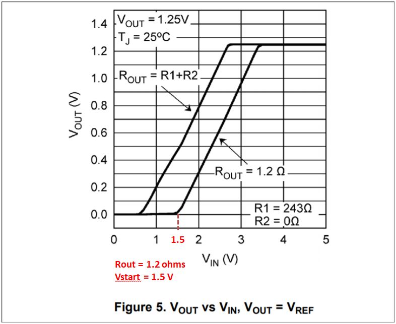
The input voltage at which your output starts to rise will depend on the load current as you can see from Figures 5 and 6 in the datasheet. At 1 A load current the output voltage starts rising when Vin = 1.5 V regardless of the output voltage.
This fact can be used to approximate the input voltage for your application's load current with the following procedure:
Determine the dropout voltage, Vdo, based on your application's load current using Figure 4 in the datasheet.
When the load current is 1 A, the output starts rising when Vin = 1.5 V. As such, the slope of the linear portion of the Vout vs Vin curve can be calculated as m = dVout/dVin = (Vout - 0 V)/(Vin - 1.5 V) = (Vout - 0 V)/[(Vout + Vdo@1A) - 1.5 V]
Since the Vout/Vin lines are parallel regardless of load current, the slope equation can be used to calculate the input voltage at a different load current:
Vstart is the input voltage when the output starts to rise. We can use Figure 5 as an example for Rout = 1.2 ohms. This gives a load current of approximately 1 A. Using Figure 4, the dropout voltage is typically 2 V@1 A load current. Now using the equation from my above post:
Vstart = Vdo@Iout - 0.5 V = 2 V - 0.5 V = 1.5 V
As shown by the graph, this is the minimum input voltage when the output voltage starts rising:
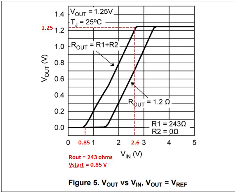
We can use the other curve on the same figure as another example, where Rout = 243 + 0 ohms. In this case the dropout voltage is calculated as Vin - Vout when the output starts falling out of regulation.
Vdo@5 mA = 2.6 V - 1.25 V = 1.35 V
Vstart = Vdo@Iout - 0.5 V = 1.35 V - 0.5 V = 0.85 V
0.85 V is approximately the input voltage at which the output starts rising for 5 mA load condition:
Keep in mind that these are approximations based on the typical Vout vs. Vin characteristics for the LM317.
I apologize for the delay. There are no problems with either configuration you listed. The LM317A is stable without any output capacitor, but TI recommends using at least 1 uF solid tantalum. Using 10 uF tantalum with an additional ceramic capacitor will further improve stability and reduce transient ringing. Keep in mind that an input bypass capacitor is also recommended for the LM317A, especially when using an output capacitor. At least 0.1 uF ceramic or 1 uF tantalum on the input will ensure stability.
I understood that Either tantalum and ceramic capacitor do not matter.
We want to use ceramic capacitor 10µF.
Vin is 24V , Vout is 3.3V and Iout=100mA
We are concerned about quiescent current at 3.3 V.
Please tell us the maximum output current when we use 10µF ceramic capacitor.
Can this IC correspond to output current 100mA when we use 10µF ceramic capacitor?
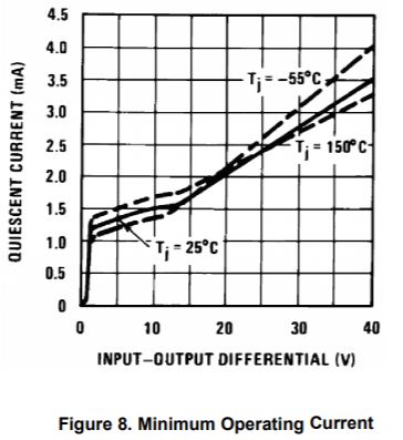
The quiescent current based on Vin - Vout is shown in Figure 8 of the datasheet. For 24 V input and 3.3 V output, the quiescent current is approximately 2.1 mA.
The maximum output current is independent of the output capacitor and dependent on the thermal metrics of the device. For your application's conditions, the power dissipated is:
Pd = (24 - 3.3) * 0.1 = 2.07 W
The Rja required for your application will depend on the expected ambient temperature. The package must be able to achieve Rja < Rja,max to prevent the device entering thermal shutdown in your application.
Rja,max = (Tj,max - Ta) / Pd = (125 - Ta) / 2.07
After determining Rja,max, refer to the Figure 39 (SOT-223 package) or Figure 41 (TO-252) to determine how much additional copper is needed on the PCB to act as a heat sink. If using the TO-220 or TO packages, you may need to mount a heat sink to the package. This heat sink should have Rha calculated with Equation 5:
Please refer to section 11.3 of the datasheet: Thermal Considerations for more information about maximum power dissipation for this device.