This thread has been locked.

If you have a related question, please click the "Ask a related question" button in the top right corner. The newly created question will be automatically linked to this question.

TPS63050: TPS63050 FB Question.

Part Number: TPS63050

Dear TI Team,

I have a problem designing the TPS63050.

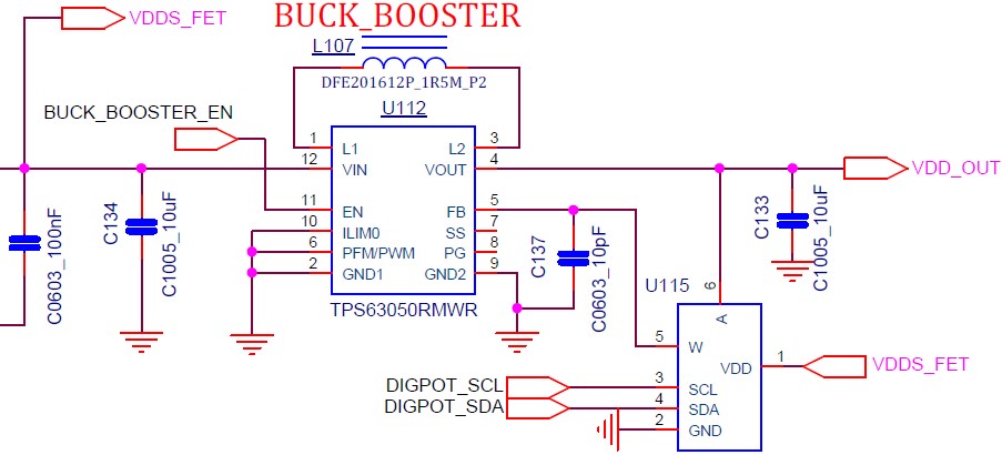
We would like to use a potentiometer in FB.
If you connect a FIXED resistor to R1 and connect a potentiometer to R2, it will operate normally up to 5V.
However, if you design R1 and R2 with the potentiometer below, the output will not rise above 3.4V.

If R1 and R2 are variable at the same time, I would like to know if the voltage and current of the FB fluctuate and cause a problem.
I want to know if there is a solution.

R1(RAW)

R2(RWB)

V_out

R_total

I_total

I_wa

I_wb

50.100KΩ

50.100KΩ

1.60V

100.2

15.97uA

15.97uA

15.97uA

68.850KΩ

31.350KΩ

2.56V

100.2

25.52uA

25.52uA

25.52uA

73.538KΩ

26.663KΩ

3.01V

100.2

30.00uA

30.00uA

30.00uA

77.444KΩ

22.756KΩ

3.52V

100.2

35.16uA

35.16uA

35.16uA

80.569KΩ

19.631KΩ

4.08V

100.2

40.75uA

40.75uA

40.75uA

84.475KΩ

15.725KΩ

5.10V

100.2

50.87uA

50.87uA

50.87uA

Thanks.


  • Hi Chun,

    i would assume that VDDS_FET voltage is around 3.3V, correct?
    The digital potentiometer port A max input voltage is usually equal to VDD. If you go higher the ESD protection start to conduct.
    In this case where VDD is 3.3V the TPS63050 output voltage would be limited to this.
    Please ensure that the VDD of the potentiometer is >= the max desired output voltage or use the potentiometer only as "R2" between FB and GND.

    Note that the accuracy of the potentiometer are typically in the +/-20% range, which will impact the TPS63050 output voltage accuracy.

    I also see that only a single 10uF Cout is placed. Please ensure that min 10uF capacitance for all output voltages are used. Consider the DC-bias effect of the capacitor.

    What is the application problem that you try to solve with this function?

    regards,
    Julian
  • Dear Julian,

    Thank you for answer.

    Let's try changing Test the VDD of the potential meter to 5V.

    application : Insulin pump

    Thanks.
  • Hello Chun,

    Please as well check the output capacitance as Julian mentioned.

    Please check as well the transient performance for your system. The capacitor connected from FB to GND will make the transient response to load changes slower.

    Please as well make sure that your system can survive the maximum output voltage on VDD_OUT. If the potentiometer opens the FB for some time, it could happen that the output voltage suddenly rises above 5.5V. For an analog potentiometer, I would recommend to add a resistor divider for the highest secure voltage in parallel to the potentiometer because analog potentiometer sometimes open when the value is changed. I do not know if this can happen with digital potentiometer as well.
  • Hello Chun,

    We haven’t heard back so we're assuming you were able to resolve your issue. If not, just post a reply below, or create a new thread if the thread has locked due to time-out.

    Thanks,
    Milos