This thread has been locked.

If you have a related question, please click the "Ask a related question" button in the top right corner. The newly created question will be automatically linked to this question.

LP2985: LP2985AIM5-3.3/NOPB regulation failure

Part Number: LP2985

Hello

I face recently failures of regulation with the LP2985, appeariing on some boards. 

The LDO is fed by a 12V supply, not well regulated, with ripple at 1kHz.

See below the startup sequence

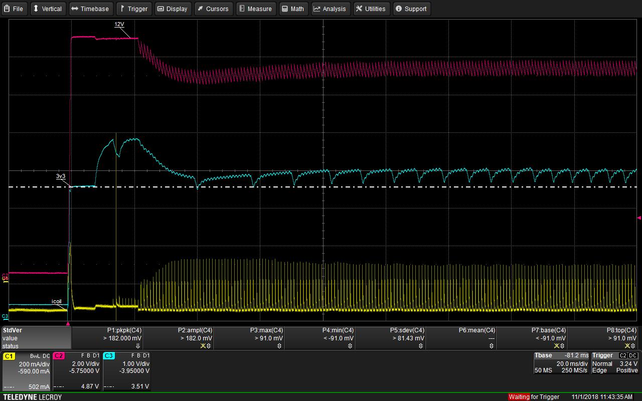
We see clearly that the LDO outpèut is not at 3.3V at startup (3.5V) and then goes up to 4.8V and then pump in regulation at 1kHz and not at all around an expected average of 3.3V.

This LDO clearly has a failure, and the lack of regulation affects also the 3V3 feeded microcontroller. Detroying permanentently the MCU, or the power stage (this board is used to regulate up to 10A / 150V)

Already checked:

1) Max LDO input unable to go higher than 14.8V (on failed boards, over the complete temperature range)

2) LDO output stability with 10uF 25V X7R cap: stable on a 20us 100mA overload pulse, each 1ms

3) At power off, output to input voltage not greater than 150mV

Do you have some advice for additional measurments to find the root cause?

Thanks

Christophe

  • Hi Christophe,

    Can you please provide some additional information:

    What are the signals at the ON/OFF and BYPASS pins? If possible, adding these to the scope shot would be helpful.

    What is the 12 V supply? Is it a 1 kHz switching regulator?

    It looks like the LP2985 is successfully regulating 3.3 V for the first 10 ms until there is a step in the current being measured on channel 1. What is this current? I see that it is labelled icoil. Is this the inductor current of the 12 V regulator?

    What is your load and what is the nominal load current? This LDO has a junction-to-ambient thermal resistance of 206 C/W and a maximum recommended junction temperature of 125 C. Assuming this board is being tested at ambient room temperature, the maximum power dissipation across the pass FET can be calculated as:

    Pd,max = (Tj,max - Ta)/Rja = (125 - 25)/206 = 0.49 W

    Depending on your nominal load current, the LDO may be exceeding this maximum power dissipation, resulting in poor regulation.

    You mentioned this board is used to regulate 10 A / 150 V. Is this LDO involved in that as well, or is it only responsible for powering an MCU?

    One thing to try is isolating the LP2985 from any kind of load and monitoring the output. If it is able to regulate 3.3 V, then it is the LDO's interaction with the load that is causing the problem. If it is not, then the issue is related to the 12 V supply.

    Thanks,
    Gerard
  • Hello

    Thanks for your fast  answer, and find additional information below:

    - BYPASS pin is left floating. And adding a 10nF MLCC on this pin to GND changed nothing

    - ONOFF pin is supplied by a pull-up on 12V, with a 5V1 zener to limit the voltage. I will check the voltage on it.

    - 12V supply is 1kHz switching, that has a linear mode by default at startup, and then the MCU regulate to limit losses.

    - Icoil is the current in the switching regulator coil

    - LDO load current is only the MCU, I will measure the value but it is not a thermal problem because we check all our designs with thermal imaging.

    - I tried on one problematic board to isolate the 3V3 load, i.e. disconnecting the MCU, but I was obliged to put a resistive load of 10mA to have a 3V3 regulation. What is the minimum LDO Load to ensure regulation?

    - Finally there is years that this deisgn is manufactured and around 15k unit in the field. Problems appear only on boards manufacrtured from june 2017.

    And I did not understand what you mean when stating that the issue could come from the 12V supply.


    Please let me know if these additional informations lead to other ideas to find the problem.

    Regards

    Christophe

  • Hello

    Here is the scope of the ON_OFF pin in green. Seems very strange. What do you think?

  • And I forgot to write that the 3V3 load is 18 to 20mA, the jitter is the slow blinking LED, i.e. no incremental load.

    Regards

    Christophe
  • Hi Christophe,

    I agree it is strange that ON/OFF and Vout have almost identical behavior. It also looks like the Zener diode not able to clamp the ON/OFF voltage to 5.1 V. The trigger for this erratic behavior seems to occur around 10 ms after startup when the 12 V supply drops slightly and ON/OFF drops significantly. To pinpoint the problem we need to find out what is causing this. There appears to be a spike in the inductor current at this time. Besides the LDO, is there anything connected to the 12 V supply that could be responsible?

    The LP2985 does not have a minimum load requirement. It should be able to regulate 3.3 V even with no load current.

    Were there any changes (design or otherwise) implemented for the boards that were manufactured in June 2017?

    Another experiment to try is monitoring the output after removing the Zener diode and shorting ON/OFF to Vin. One way to achieve this is by replacing the current pull-up resistor with a 0 ohm resistor. For the LP2985, ON/OFF can be tied to Vin if shutdown functionality is not required.

    Lastly, and I apologize for not mentioning this in my last post, but a schematic of the LP2985 in your application would be very helpful in understanding the issue. Are you able to provide this? If it is sensitive information, I can add you as a friend over E2E and you can send it to me in a private message.

    Thanks,
    Gerard
  • Hi Gerard

    I request friendship in order to share the detailed schematic in private.

    The shutdown function is used, in order to cut the 3V3 if the MCU is detected faulty. In fact the ONOFF pin is tied to the 5V1 zener through a 10k resistor. This mean that on this board the LDO is sourcing some output current. Is this normal ?

    On an other board, I found the LP2985 not regulating at all (no output) and the ONOFF pin was stuck to GND, inside the regulator, measured as a 300hms resistor to ground.

    I have some faulty boards where the MCU is detroyed, consuming 200 to 300mA, probably due to a not well regulated 3V3... but when the faulty MCu is removed from the baord, the LDO outpu nothing at all.

    Hope we can focus on the root cause with the detailed schematic.

    Another way could be your analysis of the defective LDOs, do you think you could be able to find the root cause this way?

    Regards

    Christophe

  • Hi Gerard
    For the current spike, it is a little power mosfet commutation at the MCU initialization.
    The voltage on ON-OFF pin drops to the 3V3 supply of the MCU when the pin is initialzed to push-pull output. As the voltage (green) is above the 3V3 (blue) this mean that on this board also the ON-OFF pin is sourcing current !!
    Regards
    Christophe
  • Hi Christophe,

    LDOs do not source output current. The output current of an LDO is always less than the input current it receives from the supply, because some current is used to power the internal circuitry. The ON/OFF pin cannot source current either since is a digital pin that enables the internal reference and error amplifier. It typically sinks only a small amount of current. With the additional information you have provided I am interested to see the shutdown circuit implemented on your boards. I have accepted your friend request, so please send the schematics in a private message.

    If we are unable to find the cause, I can try to reproduce your conditions with some functional LP2985 devices to identify what may be causing the failure.

    Thanks,
    Gerard
  • Hi Gerard
    I send you the schematic in PM.
    But as the ONOFF pin is an input, that actually OUPUT some current on this failed LDO, you should have an idea of what can cause this, no?
    In between I checked the V12 rise at power on, and there is no overshoot, and rise is between 3.4V/ms to 16V/ms depending on the board supply level. When all is started and the supply regulated by chopping, voltage rise is in the range 40V/ms to 160V/ms. Is this an issue for your LDO?
    But there is years that it works like this !!
    Thanks
    Christophe
  • Hi Christophe,

    It is difficult to get an idea without the schematic. There may be an issue as the ON/OFF pin for the LP2985 has a minimum slew rate requirement of 40 V/ms.

    Can you confirm if the slew rate at the ON/OFF pin is the same as the 12 V supply in your setup? Please let me know the results and retry sending the schematic in a private message. 

    Thanks,

    Gerard

  • Hi Christophe,

    As this thread is being handled through private message, I will be closing this thread.

    Thanks,
    Gerard