Other Parts Discussed in Thread: LM5160, , SN6501, TPS65130
HI
I have designed a Fly-Buck PSU based on the LM5160. I have reviewed the datasheet and some application notes about the IC such as TIDA-01427
page 18 of the LM5160's datasheet mentions some notes about the inductor selection. but I have a question in my application:
Vin: 4.5 to 5.5 Volt
dVi=75 mV (input Ripple)
Ron=332K Ohm for 260KHz
or 169K for 500kHz.
(which one is better?)
Vo1=-8
Vo2=+8
Io2=180mA
Io1=180mA
I have calculated the Inductor's currents as following according to LM5160's datasheet (page 18, 8.2.1.2.3 Inductor Selection):
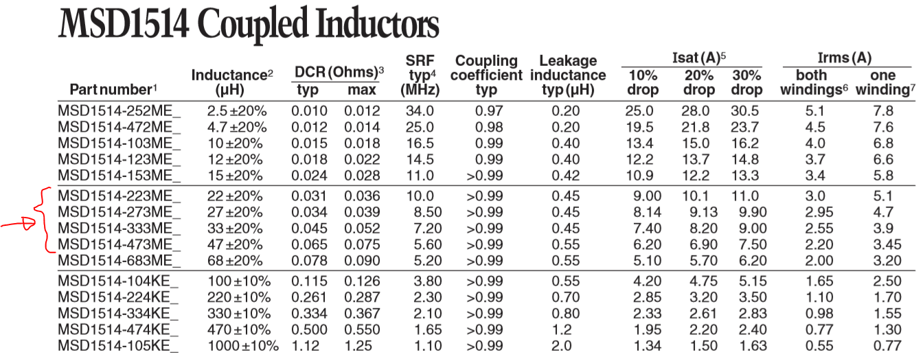
for Fsw=260 KHz, Lmin=83uH
for Fsw=500 KHz, Lmin=42uH
IL1 = 1.056
IL2 = 0.18
IL1_pk = 1.12029577464789
as you know in Fly-Buck with LM5160 the Transformer is configured in series mode.
now I want to choose an inductor in Digikey or Mouser.
for example SRF1260-101 is good or not?
Could you please help me?
Best Regards