This thread has been locked.

If you have a related question, please click the "Ask a related question" button in the top right corner. The newly created question will be automatically linked to this question.

UCD3138HSFBEVM-029: input step problem with Switching power supply based on UCD3138

Part Number: UCD3138HSFBEVM-029
Other Parts Discussed in Thread: UCD3138

Hello
I tested your company's UCD3138 full-bridge hard-switch development board and designed a 200W switching power supply prototype based on your development board.
I tested the input step waveforms of your development board and our prototype. The figure below is the input step waveform of our prototype.

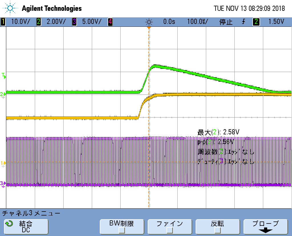
As shown in the figure above, when the input voltage jumps from 20V to 30V, the output voltage jumps up to 2.5V and the recovery time is nearly 500us.

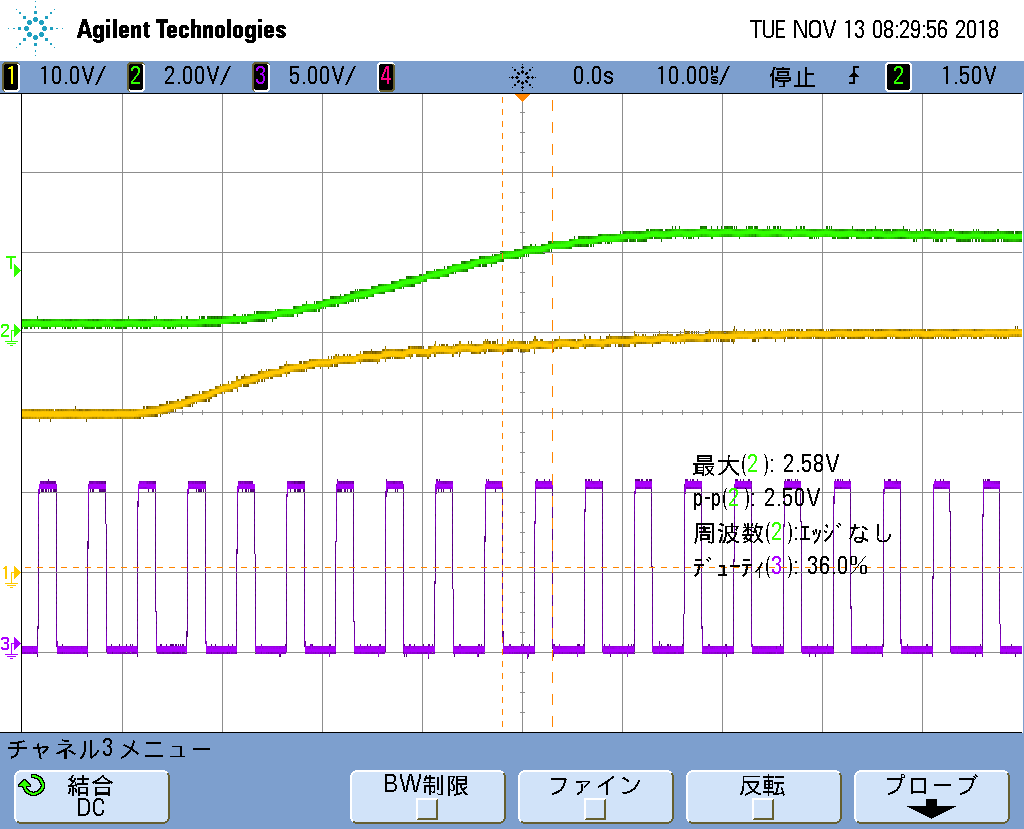
The figure below changes the timeline and expands the waveform.

It is found that the duty cycle D of the UCD3138 remains constant for 50us of the input voltage transition and does not decrease as the input voltage increases.

After 50us, the duty cycle D gradually decreases, and the output voltage gradually returns to the target value.

I tested your development board again, with a load jump of about 500mV and a shorter recovery time.
I am very confused about this.
The switching frequency of the prototype is 200 kHz, which is the duty cycle updated every 5 us. The prototype only uses output voltage feedback control and does not incorporate feed forward control of the input voltage.
I suspect that your development board should enable the input voltage feedforward function, so the response to the input voltage will be much faster.
However, I am still very confused.

Although I did not enable the input voltage feed forward and only used the output voltage feedback control, why does the feedback adjustment take place after the input transition delay is 50us ?

The switching period of my prototype is 5us, that is, there are 10 cycles of delay.

The manual introduces the PID link of UCD3138 as an analog circuit. After the initial configuration is completed, it can be run independently.

Why is the PID link that only enables output voltage feedback control delayed by 50us? Instead of real-time control, that is, after a switching cycle of 5us, start to adjust?

UCD3138 For the adjustment of the input step, is it necessary to enable the voltage feed forward function, otherwise it can not be quickly controlled?

Thank you

ZJYL

  • An expert will get back to you shortly.
  • You are right about the voltage feed forward being implemented in our evaluation module.
    This of course helps to minimize the response time to line change.

    The PID filter in UCD3138 needs only 500 nS for the calculation
    If the response to voltage input (line) transient looks exessive to you.
    Please make sure that your sample trigger positioned at 500nS before the end of the period. Also make sure that your filter coefficients are tuned for the compensation of your power stage that might be different than the one in our EVM. Hope this makes sense.
    Regards,

  • Thank you for your advice.

    I have previously adjusted the PID coefficient according to my prototype, the bandwidth is about 10kHz, which is a little larger than the bandwidth of your prototype, as shown below.

    I think the PID coefficient I adjusted is still quite suitable.

    You said "Please make sure that your sample trigger positioned at 500nS before the end of the period.", how do I determine if the sampling trigger is 500ns before the end of the cycle? I don't understand this, please advise.

    Thank you

    ZJYL

  • Excuse me, you said "ensure that the sampling trigger is 500ns before the end of the cycle", is to ensure that the PID calculation time is sufficient? Because each PID calculation requires 500ns, this will ensure that there will be a new calculated PID value for each switching cycle, right?
  • Correct,

    The value of DpwmxRegs.DPWMSAMPTRIG1.all  has to be set at least 500 nS before the end of period to ensure that the PID calculation time is sufficient.

    If this is set properly, you should see an attempt to correct the output voltage in a few switching cycles, depending on your loops bandwidth.

    If you expect correction in one or two switching cycles, then you need to implement the input voltage feed forward mechanism.

    Regards,

  • Hello, I checked the source code.
    Dpwm0Regs.DPWMSAMPTRIG1.all = (pmbus_dcdc_config[0].period)- 6240;
    Among them, pmbus_dcdc_config[0].period=20000, which is consistent with your source code. The switching frequency of my prototype is also 200kHz. So the trigger time is about 5us*6240/20000=1.56us, which is enough for the 0.5us calculated by the PID.
    I did not add voltage feedforward, just use the output voltage feedback, maybe the bandwidth of 10kHz is not big enough, resulting in 50us, delay of nearly 10 switching cycles.
    I think I should add voltage feedforward to see the effect.
    Thank you
  • I have always had a doubt in my heart.
    I have done some analog power supply before, the bandwidth is about 10kHz, only pure voltage control, will not produce such a large delay of 50us to control the input step.
    The PID of UCD3138 is an analog circuit, and the calculation does not exceed 0.5us each time.
    Why can UCD3138 delay the 50us before starting to control the input step?
    How did this 50us delay arise?
    Within this 50us, the switching power supply works in an open loop state, which will cause a large output voltage deviation.
  • If you think the output variation is large than you wants, you can adjust the KP of PID LOOP2. Also, double check input voltage forward is enabled in your test code.
  • We can help you to make your compensation loop faster. But then your output may have more ripple in it.
    Then you may use oversampling to reduce the ripple.

    Either you need to follow the above, or implementing input voltage feed forward.

  • Hello.
    Do you mean "adjust the KP of PID LOOP2" means adding voltage feedforward? And increase the Kp value of the input voltage feed forward, I can respond to the input step faster, right?
    Do you mean "double check input voltage forward is enabled" refers to the "Single Frame" function at startup?
    Thank you.
  • Hello.
    what do you mean by "help me to make your compensation loop faster"? How can you help me?
    If I told you some parameters of my prototype, did you help me design a wider bandwidth PID coefficient?
    I am very interested in what you call "use oversampling to reduce the ripple". The output ripple of my prototype is as high as 150mV, I hope to drop it to 50mV, but due to the size limitation, I can't increase the output capacitance.
    Excuse me, how can I enable oversampling? Is there a corresponding application document for reference?
    Thanks.
  • Please look at SAMPLE_TRIG_OVERSAMPLE bitfield in the register DPWMCTRL2:

    Bits 5-4: SAMPLE_TRIG1_OVERSAMPLE – Oversample Select for Sample

    Trigger 1

    00 = Trigger an EADC Sample at PWM Sample Trig Register value

    (Default)

    01 = Trigger an EADC Sample at PWM Sample Trig Register value and at

    PWM Sample Trig Register value divided by 2

    10 = Trigger a EADC Sample at PWM Sample Trig Register value, at

    PWM Sample Trig Register value divided by 2 and at PWM Sample Trig

    Register value divided by 4

    11 = Trigger a EADC Sample at PWM Sample Trig Register value, at

    PWM Sample Trig Register value divided by 2, at PWM Sample Trig

    Register value divided by 4 and at PWM Sample Trig Register value

    divided by 8

    If you set the value of this bitfield to 3, you are going to have 8 samples during the switching cycle.

    Also by playing with the following bitefields inside the EADCCTRL register:

    Bit 3: SCFE_GAIN_FILTER_SEL – Switched Cap Noise Filter Enable

    0 = Disables Switch Cap Noise Filter

    1 = Enables Switch Cap Noise Filter (Default)

    Bit 2: SCFE_CLK_DIV_2 – Switched Cap Front End Clock Divider Select

    0 = Switch Cap Clock divide by 1 (Default)

    1 = Switch Cap Clock divide by 2

    You can make the EADC run faster. And of course, your PID coefficients play a key role.

    Regards,