This thread has been locked.

If you have a related question, please click the "Ask a related question" button in the top right corner. The newly created question will be automatically linked to this question.

TPS7A16: TPS7A16 Enable Pin

Part Number: TPS7A16

Hello,

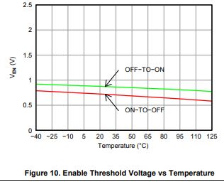
In the datasheet for the TPS7A16, it is written such that the LDO operates once the enable pin increases above 'VEN_HI' which has a minimum of 1.2V, and turns off once the enable pin drops below 'VEN_LO' which has a maximum of 0.3V. This initially did not make sense to me that the VEN_LO has a maximum rather than a minimum, as this would mean that technically some components may not turn off even when pulling the enable pin to 0V. After testing the TPS7A16 eval board (TPS7A1601EVM-046), I now believe that VEN_LO is intended to be the maximum voltage hysteresis rather than the voltage at which the LDO turns off. My biggest confusion though is that I have measured the LDO turning on when the enable pin rises above 960mV, and turning off when it falls below 840mV. The 960mV turn on appears to be outside of the 1.2V minimum in the datasheet, so I'm very confused about both specs. Can somebody please explain this to me?

Thank you,

Brett Prudhom

  • Hi Brett,

    I agree that the enable threshold specifications can be initially confusing the way they are written.  You are correct that the actual enable thresholds are typically between the minimum ON threshold and maximum OFF threshold as shown in Figure 10.

    What the Electrical Characteristics specification shows is that in order to ensure that the device registers your enable signal as a high-level, your minimum Ven should be 1.2 V.  In order to ensure that the TPS7A16 correctly registers your disable signal, Ven should be a maximum of 0.3 V.

    Very Respectfully,

    Ryan

  • Hi Ryan,

    Thanks for the explanation, this makes a lot more sense now! The confusion was because most LDOs/controllers spec the max high and min low threshold voltages, which then imply the minimum voltage the pin must be pulled above to be on and the maximum low voltage the pin must be pulled below to be off. I am pulling down multiple different enable pins using one open drain output, so they all must be diode isolated. That 0.3V is going to be a little difficult to stay under for worst case with the diode in series, but at least now I know for a fact that's what I must aim for.

    Thanks again,
    Brett