This thread has been locked.

If you have a related question, please click the "Ask a related question" button in the top right corner. The newly created question will be automatically linked to this question.

LM25066A: Definition of 78h register

Part Number: LM25066A
Other Parts Discussed in Thread: LM25066

Hello TI,

We use LM25066A as a hotwap controller on 12V main power loop.

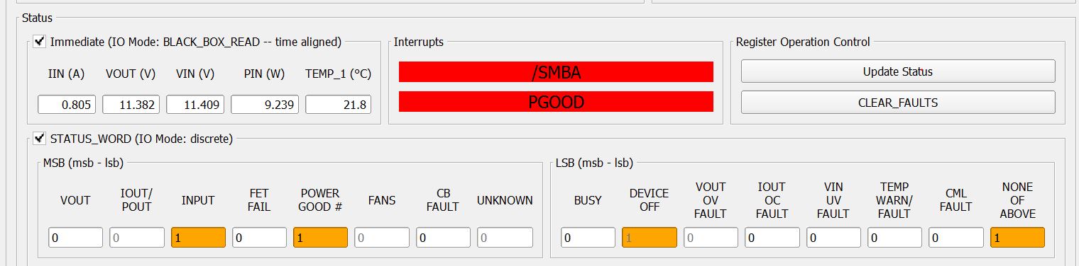
Sometimes we read ''01'' or ''03'' on 78h register after we performing short test on 12V_STBY rail.

After checking the definition of 78h register, we don't understand the DEFAULT status meaning.

If the description of the MEANING column is true, the bit status will be the default value, am I right?

If it is, the 78h reading in normal operating should be ''06'' but it shows ''01'' on GUI most.

Could you clarify what's the read back value of LM25066A 78h in normal operation? 

BR.

Stan.

  • Hi Stan,

    I will test this on our EVM and get back to you.

  • Hi Stan,

    The Default Value of the bit is shown unless the condition is not satisfied. For example, the default values of Bit-6, OFF and Bit-3, VIN UV FAULT are '1'. But, if you start up normally, the device is ON and also Vin is above UVLO. So, these bits read '0' once you update the register.

    Simply, you can say that the bits represent the current state of the respective function irrespective of the  default value. Below are snapshots of the register during various conditions.

    I have checked the below conditions on the EVM(without any changes) and GUI.

    Case:1 - Normal startup with Vin = 12V. I always see 01h after 'update Status' and never '03h'.

    The GUI shows 00h unless you click on update status option.

    Case:2- After Case-1, Click on 'CLEAR FAULTS'. Then the POWER GOOD# is cleared as well. This will also clear the NONE OF ABOVE bit as shown below.


    Case:3 - Apply continuous Short Circuit and Update Status. 

    I always see the same results respectively for each case with multiple attempts which is expected.

  • Hi Praveen,

    Many thanks for your comments. I will check the behavior at my lab.
    By the way, could you tell me where I can download the GUI that you used for this test?
    Actually I cannot find the GUI fro LM25066a like yours.

    BR.
    Stan.
  • Hi Stan,

    The name of GUI is 'PI-Commander EVM GUI'.  You can find it in the below link.

  • Hi Praveen,

    Thank you. Actually I ever downloaded this GUI but there is no button to show the dashboard and the device is not detected.

    BR.

    Stan.

  • Hi Stan,

    If the LM25066 is not detected, an option is provided to rescan, ignore, or exit the GUI. If the hardware is

    intended to be connected, check the USB connection to the PC, the FTDI connection to the evaluation

    board, and verify that the power is present on the evaluation board by measuring the voltage between the

    VIN and GND testpoints.

    Choosing the Ignore option causes the application to bypass additional attempts

    to detect the LM25066 on the PMBus and facilitates access to the GUI integrated design tool.

    For more details, you can go through EVM user guide available in the link below,

  • Hi Praveen,

    Is this GUI limited to use FTDI? Currently I only have your TI USB interface adapter.

    BR.
    Stan.
  • Hi Stan,

    You should be able to access with the TI USB interface adapter (Although we have not tried connecting  the LM25066 EVM with 'TI USB interface adapter'). Make sure you connect the SCL, SDA and SMBALERT of the adapter to the respective pins of J1/J2 on the EVM Board.

    Let me know if you are not able to connect with the TI USB interface adapter. In that case, I will check this from my side. 

    Regards,

    Praveen

    Please click "This resolved my issue" button if this post answers your question.

  • Hi Praveen,

    Thanks for your support, we will check the setting at my side.

    BR.

    Stan.