Dear E2E,
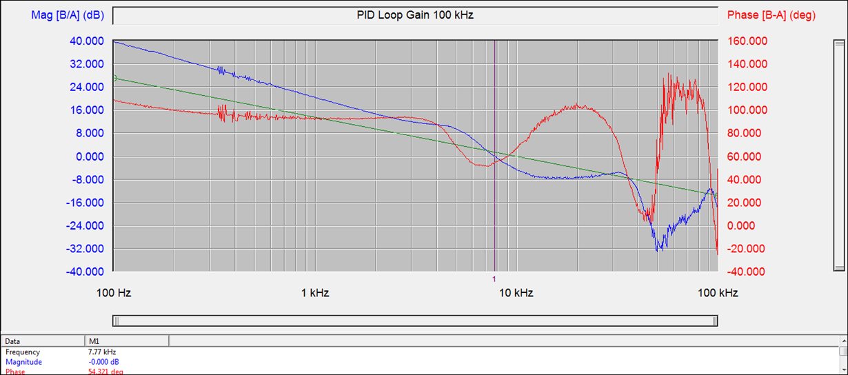
With the help of the small signal model from David Baba I was able to improve the bandwidth and the DC gain of my SSPR using the LM5115. Since the power stage response is mostly a steady -20 dB/dec slope from low frequency until beyond my target bandwidth (which was 5 kHz to 10 kHz), I just wanted a flat gain from the voltage error amp and a higher frequency pole for noise immunity and gain rolloff after the 0 dB point. I found that without any DC blocking in the feedback path of the voltage error amp, the load regulation was very poor, but with a a DC blocking cap of 10 uF in series with the feedback resistor that set mid-band gain, I got a gain and phase plot that looked pretty good:
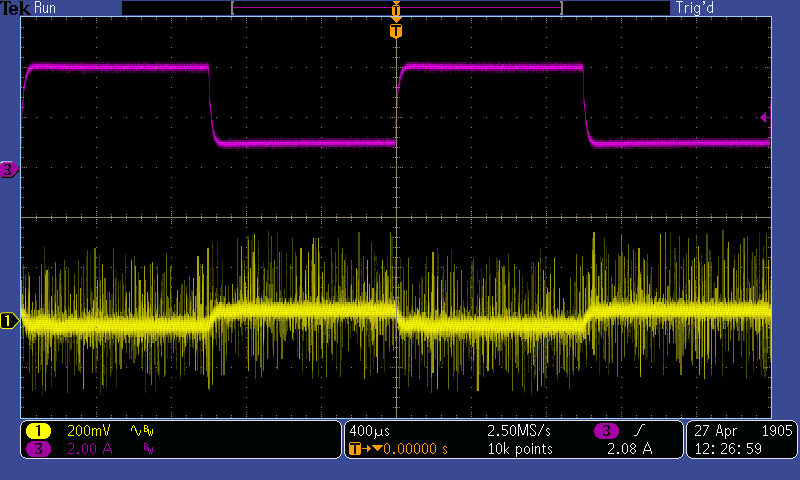
Here you can see a BW of 7.8 kHz and 54º of phase margin. But the load regulation is still poor:
Ch.1 is my output voltage, AC coupled, and Ch.3 is an e-load testing the transient response. The transient response itself is fine, but the poor load regulation is evident.
Could this have something to do with the current sense Gm amp that connects to the voltage error amp output? I have 100 pF from the two error amp outputs to GND.
Thanks,
Chris


