This thread has been locked.

If you have a related question, please click the "Ask a related question" button in the top right corner. The newly created question will be automatically linked to this question.

TPS61041: Rush current at start-up

Part Number: TPS61041

Hi,

We got a question from the customer about TPS61041.
Could you help us?

[Question]
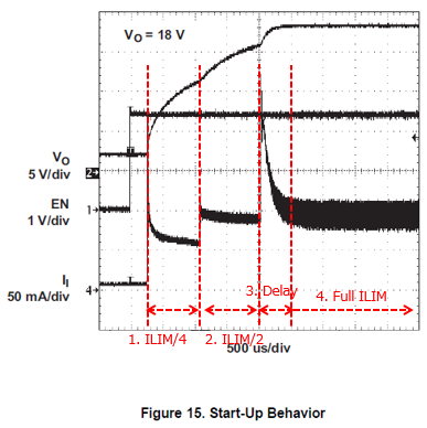
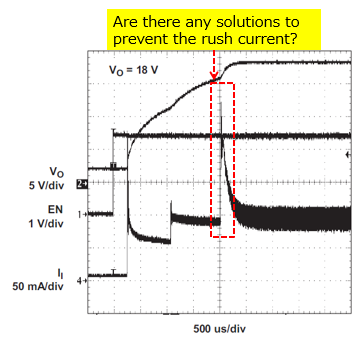
According to the datasheet, the rush current of the inductor current is occurred at start-up.

- They assume the finish of the soft start period is the reason why this phenomenon happens. Is this their understanding correct?
- Is there any solutions to prevent the rush current?

They are using the IC on thier proto type. They have problem which is the source current of the battery beyonds the rating due to this rush current. Therefore they would like to know how to reduce the rush current.

Best Regards,
tateo

  • Hi Tateo,

    the understanding is correct.The reason is that the device release its current limit to 400mA. I think you can try TPS61041, which has smaller peak current, 250mA. other solutions could be smaller inductor, such 4.7uH or lower; larger input capacitor and smaller output capacitor.
  • Hi, Thank you for your support. Let me confirm one thing. They assume Cff might reduce the rush current since it vary loop response. Therefore they would like to try to vary Cff. How much is the recommended range of Cff under the following their schematic?

    Best Regards,
    tateo

  • Hi, Are there any update on that? Sorry for rush, but could you give us your feedback by this Tuesday?

    Best Regards,

    tateo

  • Hi Tateo,

    just check if you refer to the method as in this link "www.ti.com/.../slva307b.pdf"
    I think we need a 3.3nF capacitor or higher.
  • Hi, Thank you for your reply. I need to clear my head. We assume this phenomenon is occurred by following steps.

    1. IC is enabled
    2. Start the soft-start (starting from ILIM/4 for 256 cycles, then ILIM/2 for the next 256 cycles)
    3. Delay time to enter the full current limit (this causes the rush current)
    4. finish the soft-start period (release full current limit)

    The soft-start period is determined by clock cycle(256 + 256 cycles). Therefore we assume the IC can't extend the start-up period. And the rush current seems to beyond full current limit. We assume the delay time to enter the full current limit causes the unregulated the current limit. Is this our understanding correct?

    If our understanding is correct, we need to shorten the delay time. Are there any solutions for that?

    Best Regards,
    tateo

  • Hi Tateo,
    the inrush current is 250mA, which is still below the peak current limit of this device, 400mA. that is also why I suggest 250mA device TPS61041. The current limit is the same for the period 3 and 4. the input current is determined by the loading in the period 4. it doesn't reach the current limit.

  • Hi, Thank you for your reply. The topology of this IC is peak current limit control. Please refer to section 7.3.1 in datasheet. So I believe the inductor current reaches the full current limit in the period 4.

    I think the range of Il is a typo...

    Best Regards,
    tateo

  • Hi Tateo,
    the current waveform in the startup is the input current, not the inductor current. this is why we see approximately 100mA after startup finish.
  • Hi, I think the input current is same as the inductor current. Please refer to attached file for the details.

    TPS61041 TINA Startup_18DEC18.pptx

    Best Regards,
    tateo

  • Hi Tateo,
    in the simulation, the output impedance of the power supply is zero, so all the inductor will flow through the power supply. that is why input current is the same as inductor current in the simulation.

    however, in real world, the output impedance of the power supply is normal higher than the input capacitor in the switching frequency. so the inductor current ripple will flow through the input capacitor, and the average current flows through the power supply. then we can see the difference between the input current and inductor current
  • Hi Tateo,

    I closed the post as no further repry, I assumed you had resolved the problem. just reply below if not.
  • Hi, Sorry to the delayed reply. I checked the inductor current and the input current on EVM. The inductor current smoothly move to full current limit from ILIM/2. Therefore I assume to need slow slope of the output voltage after finish the soft-start.

    So I suggest the application report(SVVA307B) to the customer. But I'm concerned the output voltage ripple is increased due to Cff is isolated by diode...

    I'll let you know if we need more help.

    Best Regards,
    tateo