This thread has been locked.

If you have a related question, please click the "Ask a related question" button in the top right corner. The newly created question will be automatically linked to this question.

TPS22860: TPS22860 switch is not correctly outputting the voltage

Part Number: TPS22860

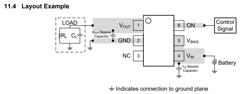
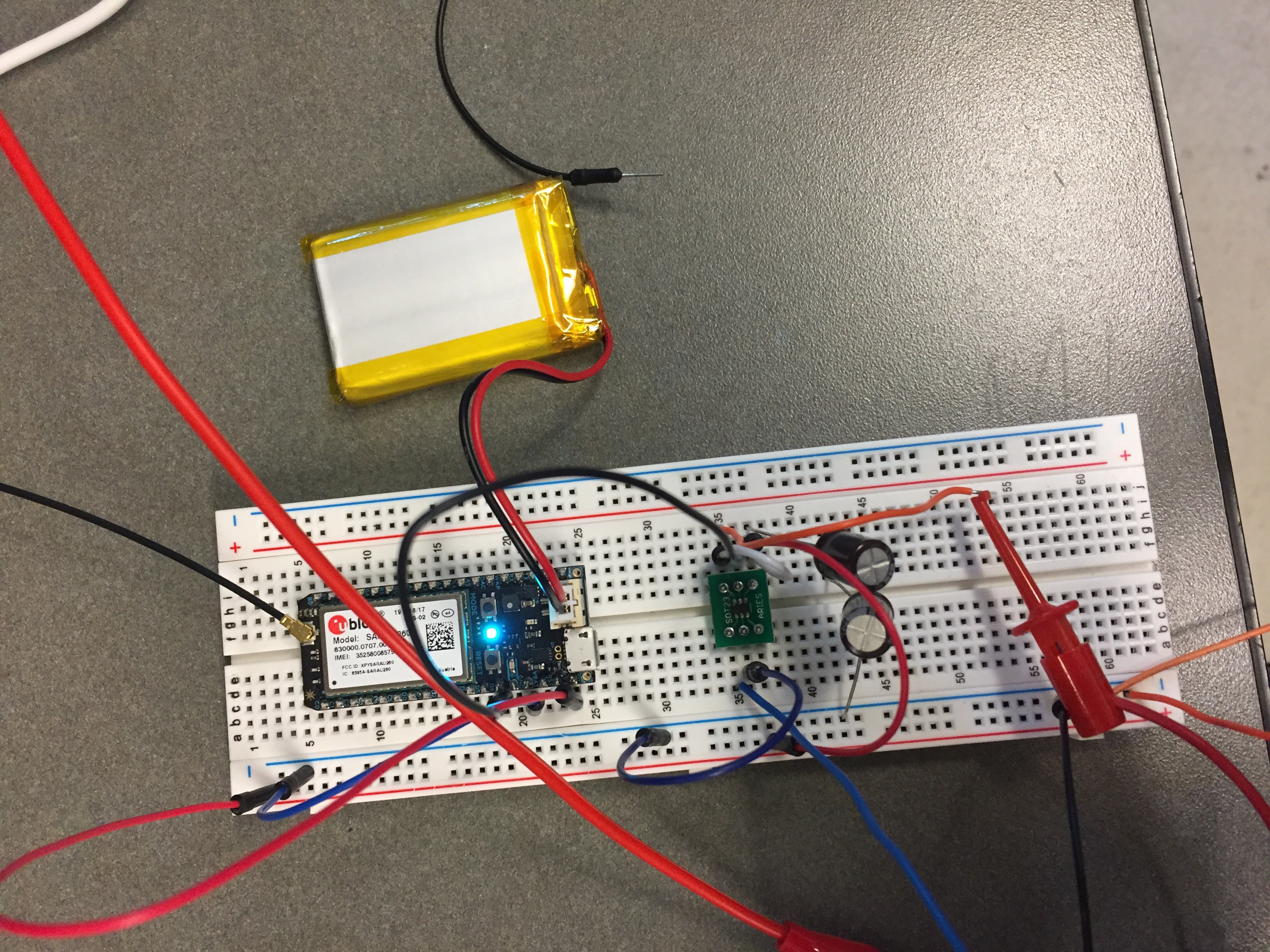
For the part, I have Vin and Vbias measured at 3.3 volts. I have Von also measured at 3.3 volts. I also have attached a 1 uF cap from Vbias to ground, and a 0.1 uF cap from Vout to GND. I followed the layout example from the datasheet. My problem though is at Vout. I expect it to be around 3.3 volts, but instead it shows close to 0 volts. I cannot figure out why. Any help would be greatly appreciated!

  • Hi Peter,

    Thanks for reaching out on E2E!

    I appreciate the detailed summary, I have a few additional questions for you that I was hoping you could help clarify:

    1. What is your output load? Have you tried disconnecting your output load and measuring the output voltage afterwards?
    2. Is VON connected to the same input supply as VIN and VBIAS, or a separate 3.3V supply? If not, can you try connected VON to a separate 3.3V supply?
    3. Can you share any oscilloscope shots with us? Any captures showing the output behavior when ON is being turned on/off would be appreciated. 
    4. Is the device facing the correct orientation? Note that pin 1 is Vout and pin 4 is Vin.

    Thanks,

    Thanks,

    Arthur Huang


    To find the latest information on Power Switches, visit www.ti.com/powerswitch

    SY6869

  • 1. My output load is a 59kohm resistor, and the voltage from the resistor to ground is 0 volts. When I take the resistor out and measure just the Vout pin, the voltage is 0.02 volts.

    2. Von is powered by a separate 3.3v source (power supply). And Vin and Vbias are powered by a different 3.3 volt power source.

    3. Here is an oscilloscope screenshot. The blue is my control pin, going from 3.3volts to 0 volts. The yellow is Vout across my 59kohm load.

    Here is the oscilloscope output when I remove the resistor (just measuring Vout without a load resistor)

    4. I believe so. Here is my hookup

  • Hi Peter,

    According to the last image, it looks like you have power connected to ON, but no power being applied to VBIAS (pin 5). What is the white wire connected to?

    Also to confirm, the dot on the device is facing top left in the image, correct?

    Thanks,

    Arthur Huang
  • The white wire is connected from the right center pin and the right bottom pin (Vbias to Vin). The black wire nearby is coming from a microcontroller to the ON pin.

    And yes, the dot is on the top left.
  • Hi Peter,

    What is your input supply for VIN and VBIAS? Do you have a current limit set on the PSU?

    Can you try repeating the same tests without the input/output capacitors?

    Have you also tried replacing the device with a new one and seeing if the behavior remains the same?

    Thanks,

    Arthur Huang
  • Problem fixed. There was a problem with the soldering. Thank you!