This thread has been locked.

If you have a related question, please click the "Ask a related question" button in the top right corner. The newly created question will be automatically linked to this question.

BQ24610EVM: Eval Board Overcharging Issue and no complete charge indication help and fix

Part Number: BQ24610EVM

Hello,


We have come across a few issues which we would like help in figuring out the Battery which was used is a:

FRIWO FB5S1P18650-28:  5S1P, With Built-in 10k NTC Thermistor Wire:

Nominal Voltage: 18.25V,

Nominal Capacity: 2850mAh,

Charging Voltage: 21V,

Discharge Cut off Voltage: 15V

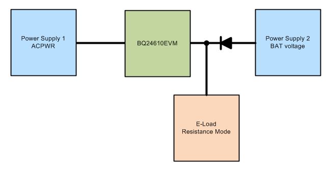
We used this battery with the Eval Board which is the BQ24610EVM. 

When Charging the charging indicator LED would be a solid on (STAT1), but we noticed when the battery voltage reached 21V the charging would continue over 21V and would not stop until it reached 22.6V whereby at that point the STAT1 led then flickers on/off every 3 seconds and on the multimeter, I am seeing the voltage is not stable and going up and down from 18V to 21V (when STAT1 is flickering), the Termination and Safety Cut-off has been enabled on JP1 by floating the pin 2 (I also, did the jumper to Pin 2 and 3, which made no difference).

My guess is that the internal battery protection lock keeps getting activated because the charger is overcharging the battery.

My issue here is that why the EVM charger board is overcharging the battery and how to fix this, also why does the STAT2 indicator (which supposed to show the charging is complete) never lights up?


Please, could I have help on how to fix this as soon as possible?


Best regards


Mo


  • Hey Mo,

    Can you monitor the VFB voltage during this test with a DC meter measurement? We want to get the FB voltage once the voltage is around 21.1V.
    This is TP13.

    Can you also describe the other jumper configurations (JP2, JP3, etc)?

    What is the input voltage in your test? What is the input source current capability?

    As far as STAT2, that sounds like the charger is going between charge in progress and some fault, without ever hitting termination. Was the resistor divider to the VFB pin adjusted on your EVM?


    Regards,
    Joel H
  • Hello,

    The Input Voltage to the charger is a 24V Medical Charger which provides 6.25A (Using the Fluke 83, the reading is 23.73V)
    JP1: floating (Safety Timer and Termination Enabled)
    JP2: 1-2 Connected
    JP3: VREF -2 Connected (Running off VREF)
    JP4: 1-2 Connected
    JP5: 1-2 Connected
    TS is connected to the NTC of the battery directly

    Things connected from battery side is:
    Negative -> PGND
    Positive -> BAT
    NTC -> TS

    Things Connected from medical Charger:
    Negative -> PGND
    Positive -> ACPWR

    LED shown when Charging:
    ACDRV
    CE
    PG
    STAT1

    No resistors or caps have been touched or altered on the EVM.

    When the Battery Voltage reached 21.18V TP13 voltage was: 2.046V (Used the Fluke 83 multimeter)

    I also Noticed that when reading the TP13 Voltage on the Fluke 83 the other multimeter which is connected parallel to the battery the voltage droped to 20.8V

    Not sure if that means anything?


    Mo
  • Also using the Fluke 83 Multimeter the voltage starts to fluctuates and the flashing begins at 21.2V
  • Hey Mo,

    Based on the battery voltage measurement, the battery is right at the regulation voltage. Do you have the measurements when you see the incorrect charging behavior? You can also measure the SRN voltage instead of the VFB voltage. There is likely a loading effect from your multimeter. However, I would expect the loading to actually increase the regulation voltage slightly by about 200mV. Those meters have roughly 10MOhm input impedance when measuring voltage so it could be indirectly causing that dip in battery voltage.

    Can you take a scope capture of the SRN voltage and the battery current? Do you also have access directly to the cell, or is does the battery pack integrate the protection devices without access to the direct cell voltage?

    Please also capture a scope capture of charging current if possible. I would be curious to see what is happening in time.


    Regards,
    Joel H
  • Hello,

    We do have a basic 60MHz oscilloscope, but just with the standard probes. I'm not sure on how to scope capture the charging current. 

    If you could advise me it would be helpful.

    I can scope capture the voltage from SRN, unfortunately, the battery pack is sealed and has no access to the cell, the protection is integrated inside the battery pack.

    What I could also do it scope capture the voltage as it is charging the battery?

    Mo

  • Hello,

    I am using a Tektronix TDS2002, with 2 passive probes TPP0201.

    I took reading on the oscilloscope from the battery (reading the SRN is connected to the battery line).

    On Channel 2 I took the reading from the TP13 pin as you can see there is a blip which happens which is very small.

    Would it be best that I change the resistor values to a higher tolerance 909K like a 0.1% version?

    Mo

  • Pleases check the reply as follows
  • Hey Mo,

    Measuring the battery current would be done with a current probe around the current carrying wire or a differential probe measuring across a low resistance sensing resistor. Without either of those, another option is just to do a DC current measurement. I would suggest using a sensing resistor and measure voltage instead of putting your current meter in series with the battery directly. This can have undesired effects.

    I am also confused by your waveform. The SRN voltage is only rising to 1.5V max or did you add an offset to the measurement? VFB on Channel 2 will only be a proportion of VSRN so you will see a similar waveform. To me, this looks like the battery is not even connected.

    Can you use a different battery without a protector in your testing? If not, please try to use a bidirectional power supply set to a similar voltage as your battery and see if it sinks current. If you do not have a bidirectional supply, you may also consider using a high power resistor to ground connected to SRN. From SRN you would also need a diode from a normal power supply that will forward conduct towards SRN. Once this is setup, you will want to slowly raise the power supply voltage such that the charger will push current into the resistor before the power supply does.


    Regards,
    Joel H
  • Hello,

    Yes, I did put an offset channel 1 was - 20 div offset (-20v), channel 2 was - 11.64 divs (-2.33V).

    This is the only battery we have.

    We don't have a bidirectional power supply, but we do have a power supply and load test supply,

    We also have a chinese made battery charging and discharge test box which we can also run a test with the battery lockout points.

    Also for the load test can you provide me a simple diagram for me to wire up the equipment.

    I've ordered a 0.01 Ohm 1%  3W and 5W Resistor to use as a current sense, which will come in a few working days.

    Mo

  • The Equipment we have is:

    Itech Power Supply: IT6322A

    Itech DC Electronic Load: IT8511A

    ZKE Battery Tester Electronic Load EBC-A10H

    Oscilloscope: 

    The Tektronix ones shown earlier

    Siglent: SDS 2202X with 2x SP2030A Probes

    Multimeters:

    Fluke 83

    Maplin Precision Gold WG020 

  • Hello,

    For the time being I did one test with the battery directly with the IT6322A Power Supply to see where the battery cuts off.

    At the moment the battery cuts off at 21.449V for its over voltage cut out, the the PSU goes from constant current to constant voltage after that point.

    I will run another test tomorrow, with the PSU meter connected parallel and see the reading when it goes to complete charge from the EVM.

    For your last paragraph, would you be able to draw a diagram to help me understand how to connect things, to make sure I don't make a mistake?


    Mo

  • Hey Mo,

    Feel free to use two power supplies and your DC E-Load for this test. Please see the configuration below:

    Power Supply 1 is your input.

    Power Supply 2 is generating the battery voltage but if the charger works correctly, it will not source current into the E-Load. In case it is the EVM for some reason, I would limit set a current limit on Power Supply 2. 

    E-Load should be in resistance mode and set to a low resistance value. This will be sinking the current a real battery would while PS2 is supply the "cell voltage".

    If you see PS2 going into current limit and E-Load 1 not providing current, it could be something wrong with the EVM. Also try moving the PS2 voltage up and down while monitoring the voltage on VBAT (TP9). If VBAT is at or near 21.1V, you will likely see little to no current from the charger into the load and PS2 will start sourcing current into the E-Load.

    This should clear up whether this is a battery or charger problem.

    Regards,

    Joel H 

  • Hello,

    I did a battery full charge using a PSU (at 1A)  until the lockout enabled, then fully discharged it at 1A using the E-load test (CC) again until the batteries locked out. I then again did a full charge using the PSU but this time made sure to charge at 2.6A.

    After that I then connected the battery to the EVM, this time round the battery worked correctly and the STAT1 LED turned off and the STAT2 LED turned on.

    I followed your instructions given in your last post for the EVM test, but the charging did not enable.

    I set the voltage on PSU2 as 18V and the current as 0.8A. The E-load was set to CR (Constant resistance) at 30 Ohms. The diode used are UF4001 (1A rectifier)

    Is it possible that the properties of the battery changed during the charging cycle, and caused the EVM board to function correctly?

    Mo

  • Hey Mo,

    It is difficult to say what changed. Perhaps a protection circuit in the battery pack tripped and wouldn't allow the pack to accept current but that is speculation.

    As far as my test, two notes: I should have been more specific with the value of "low resistance" in that 30-Ohms is too large given the current. If you push 1A into the E-Load, the voltage will try to shoot up to 30V. By low I mean less than 15-Ohm give or take.

    The second thing is that in using the power supply, you do not have the battery thermistor connected. You will need to apply a 10k to TS and GND in order to mimic a thermistor at a normal temperature.


    Regards,
    Joel H
  • Hello,

    It now started to work well, I did made a change to the resistor value to 887K this helped to resolve the issue due to the original setting being too high. 

    Thank you