This thread has been locked.

If you have a related question, please click the "Ask a related question" button in the top right corner. The newly created question will be automatically linked to this question.

LM5041: LM5041 Evaluation boards

Part Number: LM5041
Other Parts Discussed in Thread: LM6142, TL431

Dear sir,

I have some doubts regarding LM5041 evaluation Board working.

1. Why LM6142 used as an error amplifer iopamp?. is there any problem if we are using TL431 as error amplifier?

2. What is the use of D12 connected between pin 1 and Pin 2 of U4A?

3. I have simulated the  gate driver circuit of LM5041 in LTspice but i am not getting the correct drive voltage. Why i am not getting the correct drive voltage in LTspice simulation?

Please find the attached file for the simulation and waveform in LTspice for your reference.

Kindly clarify my above doubts.
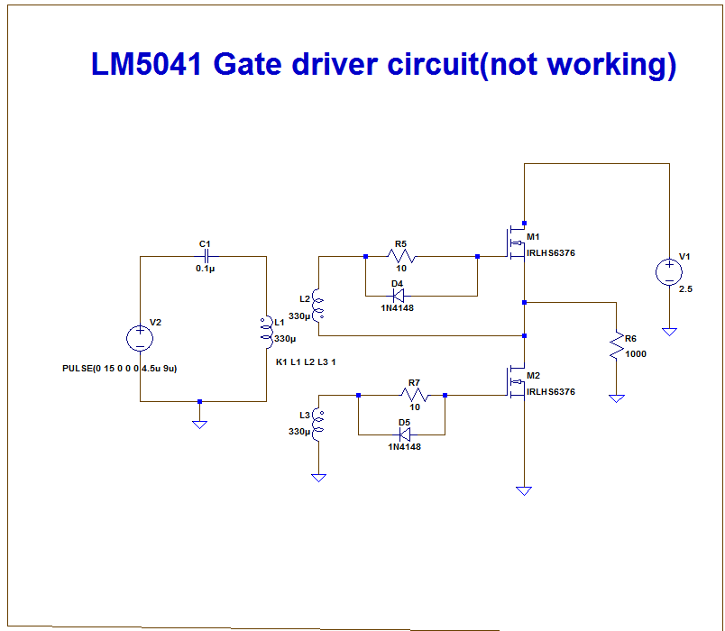
Regards

Aneesh

  • Hello Aneesh,
    I agree with you about the feedback network used on the LM5041 EVM. The designer has used some complex two stage network with the LM6142 opeamp and an LM4041 reference. It can be designed much simpler with the conventional method that uses the TL431 error amplifier.
    I guess this circuit demonstrates the flexibility that can be used in electronic circuit design.
    The two diodes used in the D12 package are used to limit the output of U4A to about 1.4V. This will result in a faster transient response by keeping U4A out of saturation.

    You should open another post about your simulation issue but I can tell you that the gate-source of M1 and M2 are floating in your circuit.
    Please close this post and open another if placing a 10k gate to source resistor on M1 and M2 does not fix your simulation.
    Regards
    John