This thread has been locked.

If you have a related question, please click the "Ask a related question" button in the top right corner. The newly created question will be automatically linked to this question.

UCC28056: Question about circuit with the UCC28056

Part Number: UCC28056
Other Parts Discussed in Thread: TIDA-01623,

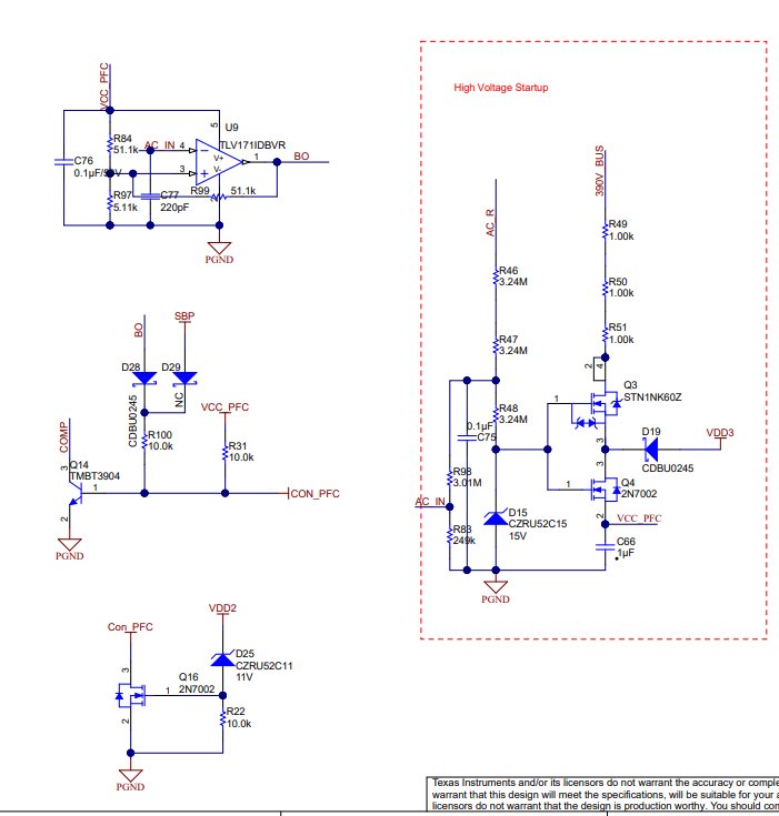
I want to build an AC/DC circuit using the design TIDA-01623 as reference: http://www.ti.com/tool/TIDA-01623#technicaldocuments. In the schematic (www.ti.com/.../tidrxg9) I don't understand the "High Voltage Startup" circuit and also the other circuits included in the uploaded picture. Could I get some help understanding this? Just a brief explanation of the circuit operation.

Best regards!

  • Should R49, R50, R51 really be 1k? Seems like VCC_PFC will will be very high if the voltage drop over R49, R50, R51 isn't enough. The UCC28056 draws 46 uA during startup which means their voltage drop is really low, and the voltage at VCC_PFC is >300 V. Am I thinking about this wrong?
  • Hello Nicholas,
    High Voltage Startup Circuitry:

    The high voltage startup circuit is connected through the rectified line voltage through R46, R47 and R48. That is FED to the D15 15V Zener will reach 15V max during power up.

    Resistors R46, R47, R48, D15, Q4 form a series pass regulator to power the PFC. The voltage at VCC PFC is 15V –VgsthQ4.
    I am not sure what the function of Q3 is. It may have been added to use lower rated voltage FETs. D19 is used to ensure that VDD3 is a Schottky diode drop above VCC_PFC. The designer most likely did this to ensure that the controller supply VDD3 comes up at the same time as the PFC controller.

    Resistors R49 through R51 are current limiting resistors.

    Capacitor C75 is a filter capacitor for high frequency noise.

    Resistor R98 and R83 form a resistor voltage divider that is used to sense the line voltage (AC_IN). The AC_IN is FED to an input under voltage or brown out comparator.

    Hysteretic Comparator with BO output.

    This is an input under voltage or brown out comparator. If AC_IN is less than roughly VCC_PFC*R97/(R84+R84) BO is high. If AC_IN is greater than VCC_PFC*R97/(R84+R84) BO is low.

    Please note that resistor R99 is used for hysteresis and the TLV171UDBVR data sheet should provide some guidance for setting this resistor value and how to calculate the hysteresis.

    PFC Disable Circuit Controlled by Q14:

    Pulling the COMP low will disable the UCC28056 controller. So if any of the following signals BO, SBP, VCC_PFC and CON are high COMP will be pulled to ground and disable the PFC.

    The last circuit looks like a rough OVP circuit:

    If VDD2 is 11V + Vgsth Q16 Con_PFC will be shorted to ground. This signal most likely will tell the PFC to disconnect. The node at Q16 drain is labeled Con_PFC. Which might be short for connect PFC.

    Regards,
    Mike
  • These resistor should just be for startup to trickle charge VDD capacitors. Once the Bias supply is up an running Q4 should turnoff.

    Regards,

    Mike