This thread has been locked.

If you have a related question, please click the "Ask a related question" button in the top right corner. The newly created question will be automatically linked to this question.

BQ500212A: Comm+ having dc offset, Vcc having noise like the gate signal during standby

Part Number: BQ500212A

Dear Supporting team,

For my bq500212a, the gate and coil voltage signal is fine as the datasheet with 80ms pulse and 300ms rest under led mode 2.

The led2 keep ON and led1 and 3 are Off which response as fault.

Two behavior are strange on the board.

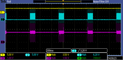
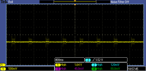
1. The supply voltage is having pulse (like the gate signal) on top of the 3.3V

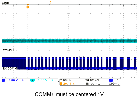
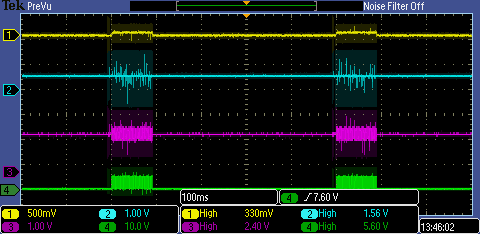
2. The comm+ signal is having offset, and pulse. which is the most different from correct discharge behavior.

I checked the demodulation circuit and the value are same with reference design. I did not use the diode on board as I notice later that its not included in "PWR550" design.

I wonder if my pulsed noise on Vcc will have serious problem?

Also, what are possible problems on the Comm+?

Thanks and Best Regards,

Calvin

  • Hello
    "The led2 keep ON and led1 and 3 are Off which response as fault." -- When does the RED LED turn ON? Does it flash before staying ON?

    Noise on the 3.3V is common, probably not a problem.
    Diodes on the Comm are clamp to prevent damage if a large spike is present. Not a problem in the 5V systems.
  • No, it turn on at once and stay.

    I'm not sure what the demodulation does. I guess the 4.7nF cap should filter out the dc? but it shows the above behavior.
  • Hi Bill,

    After some time, i found my comm+ signal is from the point after the series cap. which seems different to reference design that getting the coil voltage.

    I put the connection before series cap but the waveform still the same.

    yellow trace is the supply

    blue is the coil voltage after the series capacitor

    pink is the comm+ signal.

    Thanks and regards,

    Calvin

  • Hello
    The comm+ signal looks OK.

    A fault that turns on without flashing could be issue with current sense amplifier, input to pin 42.
    Also make sure pin 1 is grounded with a 10k resistor and no connections to comm+
  • Thank you for your reply,

    Isense connection is good. Pin 1 is grounded with 10k ohm.

    Now both LED1, 2 turn on which should be in stand by mode. However, the comm+ and coil voltage did not response when the receiver appears <5mm above. I have tested the receiver with TYLT VU SOLO. So the receiver is fine.

    I have a question about comm+ waveform in slua635a. should this pulse signal appears all the period during standby and transfer?

  • The RX Comm looks correct, the serial data rate is 2kHz.
    COMM+ will have a DC level of about 1.5V and the lower half of the waveform is used for demodulation of signal.

    Also the TLYT VU Solo is a BQ500212A based design.
  • I have both LED1,2 ON but could not work with the receiver.

    Here are the TX plot. Ch1: Isense, Ch2: Vsense, Ch3: Comm+, Ch4: Vcoil

    As you suggest, I tried to probe on different pin on the TLYT TX. and they look different from mine.

    CH1: comm+, Ch3: Isense, Ch4:Vcoil

    Ch3: Vsense, Ch4:Vcoil

    i) My COMM+ signal is also 1.5V when its not pinging.

    ii) My Isense is non zero when its pinging and opposite with TLYT

    Would you have any idea of what problem I may have?

  • We can move the trouble shooting discussion off line.
    I will send you a message and we can set up a private conversation.