This thread has been locked.

If you have a related question, please click the "Ask a related question" button in the top right corner. The newly created question will be automatically linked to this question.

PTH12040W: Error while using PTH12040WAH module.

Part Number: PTH12040W
Dear Support,


We have been using the PTH12040 for some years.

This has worked well over the years but recently we have used the module in a slightly different manner which has exposed another issue.

We have found a problem while using PTH12040WAH module.


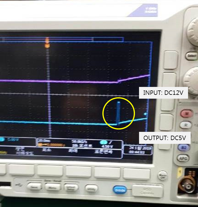
When set to IN PUT VOLTAGE to DC12V and OUT PUT VOLTAGE to DC5V 5V, we could see the initial voltage of output voltage DC 5V has risen up to 9V, 250m/s as max.


(please see the attached photo for your reference.)


I have not found the exact cause of this problem, if you have any similar case in the field or know the cause of this issue, please kindly advise us.


And regarding this, is there any material I can refer to?


We are looking forward to your feedback soon.


Best regards,


H.W.Park.

  • Hello H.W. Park,

    Could you please share your schematic?

    In your scope shot I see that the output voltage channel vertical scale is 5V/div. What is the scale on the input channel and what is the input voltage when this pulse on VOUT happens?

    Cheers,
    Denislav
  • Hello Denislav,

    Thanks for your reply on this issue.

    Here is our answer.

    1. Scale on input channel : 10V/div

    2. Input voltage : 12V

    Best regards,

    H.W. Park.

  • Hello H.W. Park,

    Thank you for the schematic.

    Questions:


    1. What is the PTH_INHIBIT signal when this pulse occurs?

    2. Have you tried using the UVLO Prog pin to set a higher UVLO threshold? See table 4 in the datasheet for some values. 

    3. Where is V1_Sense connected?

    4. Where is Sense_Rtn connected?

    5. Is the TRACK pin floating or connected to any other circuit?

    6. Could you send us another oscilloscope screen shot that shows the reference level for each waveform?


    Cheers,
    Denislav

  • Hello H.W. Park,
    I am just checking in to see if you have any updates on the questions above.
    Cheers,
    Denislav
  • Hi Denislav,

    Thanks for your reply on this issue.

    I am sorry for not getting back to you sooner. We was Lunar New Year's holiday.

    Here is our answer.

    1. The PTH_INHIBIT pin is floating.

    2. We don't use UVLO prog pin.

    3. V1_Sense is connected to end of load terminal(V1+).

    4. V1_Rtn is connected to end of load terminal(GND).

    5. The TRACK pin is floating.

    6. Unfortunately, we couldn't get oscilloscope screen shot  any more because the PTH12040WAH module was broken when we replaced the PTH12040WAH module.

    Thanks.

    H.W.Park

  • Hi H.W. Park,
    After the module was replaced, did the new part have the same behavior?
    Regards,
    Denislav
  • Hi,


    We are already using this module on our many projects and have experienced this symptom first.

    This symptom doesn’t report from end user after replacing the module.


    Best regards,

    H.W.Park


  • Hi H.W. Park,

    I am glad the issue went away after replacing with a new part. Please let us know if you get this symptom again on another part.
    You can post here again and we can help troubleshoot with more waveforms available.

    Cheers,
    Denislav
  • Hi,


    Thanks for your reply.

    But we would like to get your opinion that what is root cause on this symptom.

    Our system is required high-reliability so we must provide any solution to our end user to prevent this symptom again.

    I think you are more expert than us about this module.

    Please give us some clues.


    Best regards,

    H.W.Park

  • Hello H.W.Park,

    Initially, I thought the feedback connection (Sense+ line) may be intermittent or open, but the module does have additional safety for that condition with internal resistor connected to the Vout node.
    Another thought is some pre-bias condition on the output through a leakage path. Check if there is any parasitic path to the output from another circuit in the system.
    It would be useful to check the switch node when this happens and see if the output jump comes from unwanted switching action during this time or some other circuit.

    It is difficult to troubleshoot without some additional scope shots. If you still have a part that shows this behavior or see it again we can get more data and narrow down the root cause.

    Cheers,
    Denislav
  • Dear Denislav,


    Thanks for below your response.


    However, end-customer is thinking that they used defective product like DOA from the beginning.

    And they asked us to check if defective product is filtered out in the test line of TI, before released.

    If not, we would like to know what external environment or influence could cause a good product this kind of error.  

    If you have any opinion regarding this, kindly include any other information you feel would be pertinent.


    We are looking forward to your feedback.


    Thanks,

    H.W.Park

  • Hello H.W. Park,
    All modules go through final operational test before they are shipped out. It is not possible for a failed unit during final test to ship out.
    In terms of external environment, if there is some pre-bias condition on the output through a leakage path, the output could be pulled up.
    If we have another unit we can troubleshoot, it would be useful to check the switch node when this happens and see if the output jump comes from unwanted switching action during this time or due to some external circuit.
    If you do get another unit with this behavior, please don't discard it and let us know - we can help troubleshoot the whole circuit.
    Cheers,
    Denislav
  • Hi,


    Thanks for your message below.


    In your response, you said “In terms of external environment, if there is some pre-bias condition on the output through a leakage path, the output could be pulled up.”,

    do you mean that something else through leak path affect the output and due to this, module could be broken in the certain conditions?


    Could you explain this in more detail?


    Best regards,

    H.W.Park

  • Hi H.W. Park,

    Yes, usually if there is a pre-bias on the output from external circuit, the regulator will back off and not switch until the pre-bias voltage is lower than the programmed output voltage. In the scope shot it looks like VOUT is pulled up high very quickly, then drops and ramps up slowly. The question is where this VOUT pull-up is coming from - is it due to external circuit/leakage or due to the regulator switching. We can't tell for sure without additional scope shots. I wonder if there is another path to the output from another circuit that could pull it up.

    Let me know if this makes sense.

    Cheers,
    Denislav