This thread has been locked.

If you have a related question, please click the "Ask a related question" button in the top right corner. The newly created question will be automatically linked to this question.

BQ76930: BQ76930 - Components for ESD reinforcement

Part Number: BQ76930
Other Parts Discussed in Thread: TIDA-00449

Hi,

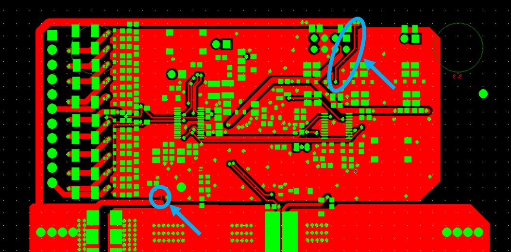
Could you take a look our schematic & kindly advise about the below questions please?

1. ZD10 : Could we add a zener diode (36V) on the track between VC10X & VC5X?

2.  ZD11 : Could we add a zener diode (36V) on the track between VC10 & VC5X?

3. ZD12 : Could we add a zener diode (36V) on the track between VC5 & VSS?

*For above ZD10, ZD11 & ZD12, I am going to use MMSZ5258B (https://www.diodes.com/assets/Datasheets/ds18010.pdf)

4. C59 & C60 : Could we add these 2 capacitors (0.1uF 50V) as a serial connection on the track between VSS & VC10?  

BQ769300 - ESD for 10S.pdf

  • Hi Chibeom,
    While it is an older document and written for a different part family, a good description of avoiding ESD in a battery electronics circuit is www.ti.com/.../slua368.pdf. This may help understand potential problems. Following the principles in this document, if you are experiencing damage to the IC, look for current paths through the IC. If you are experiencing a disruption of operation, look for transient voltage on the pins, or between ground references. Fast transients on power can disrupt some circuits, the large size of C28 and C29 may cause them to be placed far from the IC allowing the pins to move more freely. Consider the need for small capacitors near the package. Pins driven below their reference violating abs max can disrupt an IC circuit. Low voltage signals include ALERT, SCL, SDA, CAP1, REGOUT. Check for movement or possibility of movement of GND connections from the high current or coupling into traces after the filter capacitors. While reset is defined on the power pins, disruption of the supplies can upset a circuit, CAP1 is most likely to cause a shutdown in bq76930, disruption of REGOUT would likely cause it to re-start.
    In the schematic the ZD4 transient protection on the SMB lines goes to signal reference, this would seem to put transient currents into the signal ground potentially causing differential voltages on the IC pins during tranisent. Also REGOUT pull ups are connected on the same node. These would be best on the protected side of the protection components. While the R51 and R52 are large it is best to avoid directing current into more sensitive circuits. You might look for other situations like this in the circuits.

    On the specific questions:
    The MMSZ5258B should be a good general purpose zener diode. Zener diodes are typically intended for regulation. TVS diodes are intended for clamping transient events. You should check with your preferred diode suppliers about suitability for your intended operation.
    1. ZD10 should not hurt, it has the best potential benefit near the IC pins. An equivalent for VC5X to VSS might be considered if the disruption is experienced since that is the group which user communication. the upper group would re-start if only it were disrupted.
    2. ZD11 should also not hurt but may not help if ZD10 is used since D1 will limit VC10 to VC10X. Placement and coupling may be concerns though. VC10 is a sense input.
    3. ZD12 should not hurt but may not provide much benefit. VC5 is a sense input.
    4. VC10 is a sense input. The additional filtering should not hurt operation but may not be helpful.
  • Hi,

    Thanks a lot for your detailed advice. This is so much helpful.

    Apart from your advice about the schematic, I would like your another help for the design.

    While I look at the Gerber design source of your TI EVM board, I see the GND tracks that I highlighted with 2 blue circles & arrow marks are very thin & narrow.

    Is this design purposed for anti-ESD reinforcement?

    Thanks in advance!

  • Hi Chibeon,
    The design in question appears to be TIDA-00449.
    The left bottom feature is the net tie connecting the signal reference "ground" connecting to the high current BAT-. It is mentioned in the design guide and shown in figure 31. It avoids high currents influencing the low level signal reference.
    The upper trace is an ESD ground for signals on J7. There are several in that area for zeners intended to clamp transients which seem to be rather narrow. These components are typically to aid in ESD performance of a board, but the design guide does not indicate ESD performance level.