This thread has been locked.

If you have a related question, please click the "Ask a related question" button in the top right corner. The newly created question will be automatically linked to this question.

WEBENCH® Tools/BQ34Z100-G1: unable to read the correct current , due to changing the sense resistor type

Part Number: BQ34Z100-G1
Other Parts Discussed in Thread: BQSTUDIO,

Tool/software: WEBENCH® Design Tools

hello ti,

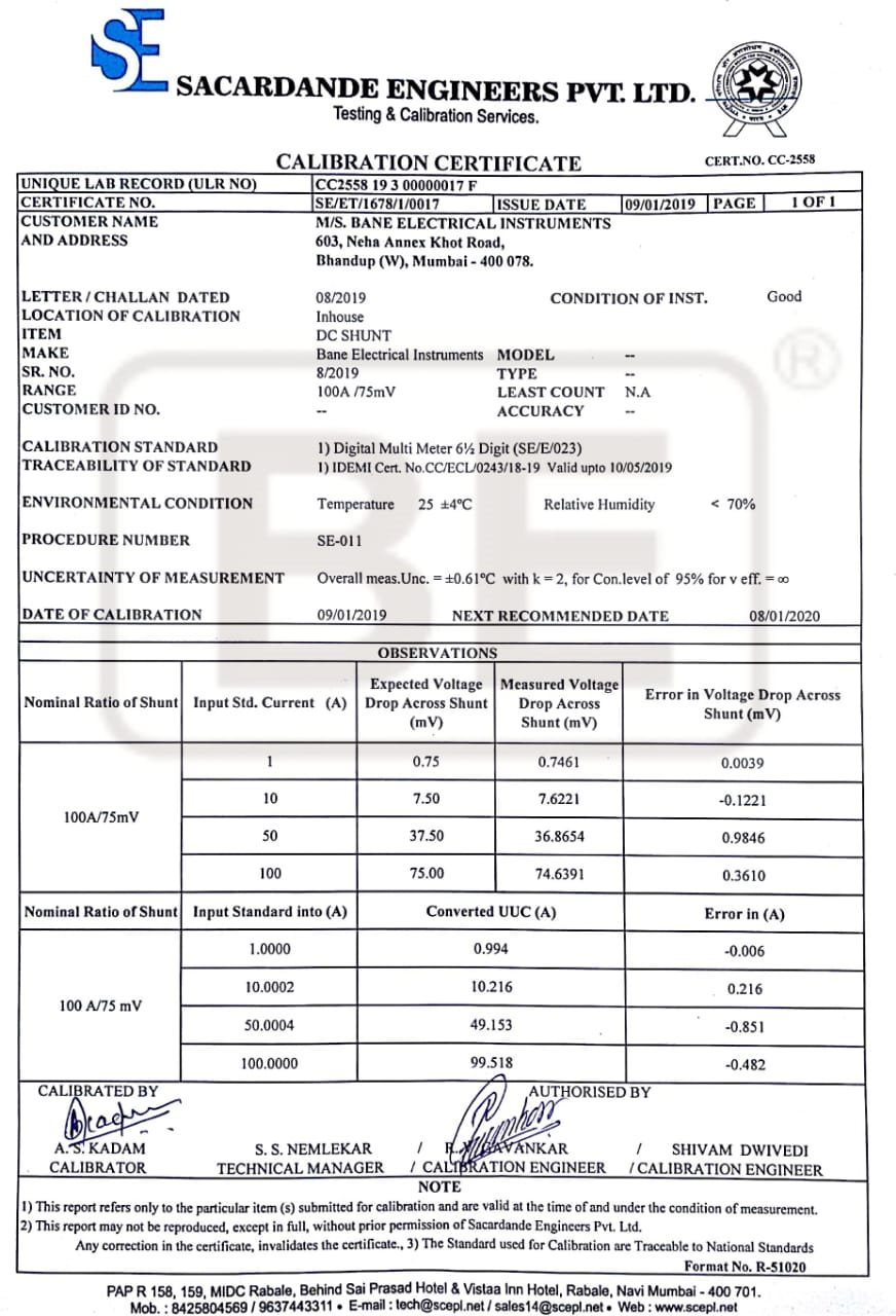
actually my task is to read the high currents i.e above 10a to 100a . so we removed the 10m ohm smd type shunt resistor and replaced 10 mohm shunt type of  bus bar which with stand upto 100A .

So i applied the charging current of 0.16Amp to battery , but in bqstudio software it showing 2.6 A  . what is mistake we doing ? or any modifications to do in register settings .

  • Hi Manoj,

    Please perform CC offset and board Offset calibration.

    Once complete, perform current calibration: training.ti.com/bq34z100-g1-current-calibration

    Sincerely,
    Bryan Kahler
  • Hello Bryan,

    Thank you for the suggestion , I calibrated the current and updated the calibration section with applied current.

    The current value is correct only for the first time and showing random values when the power is removed and reconnected for multiple times.

    i.e for example: if  current is  -446 mAmp ,  it shows -625 mA , if current is 170 mAmp , it  shows 203 mAmp

    please suggest a solution for this?

    Regards,

    Manoj

  • Hi Manoj,

    Please ensure that CC offset and board Offset calibration are performed prior to current calibration.

    If this is the case, and errors still persist:

    Please attach the datasheet of the current sense element being utilized. If you don't wish to attach it publicly, please send it to me in a direct message through the forum.

    Are you using the EVM? If not, please also share the schematic, bom and layout of the system. This may also be sent in direct message through the forum if you would not like it to be public. Please also send your SREC and gg file from before calibration and after calibration so I may view the values and how they change.

    Sincerely,
    Bryan Kahler
  • hello bryan sir ,

    as per your suggestion ,first step ,  i calibrated cc offset and board  offset with no load condition.

    After this step  without doing current calibration , i applied discharge current of -440 mAmp to battery ,but i observed the -5645 mAmp random value in bqstudio.

    so , after this i done current calibration i.e in calibration current value i entered -440 mAmp . and calibrated gas guage .

    I checked after removing power and reconnected the battery , , i  observed --330 mAmp for 440 mAmp , for charging current 160 mAmp , observing 110 mAmp in bqstudio.

    I am attaching 3 srec files for your observation 1)without any calibration 2) with cc offset and board offset calibration 3) after current calibration .

    srec_file_fr_current_calibration.rar

    we developed same sample board using bq34z100-g1 evm schematic . only change we made is removed smd shunt and placed bus bar shunt .

    we purchased the bar shunt with  local dealer which supports upto 100 A.

  • Hi Manoj,

    Do you have a datasheet? If not, please at least share what the resistance of the bar shunt is and ppm. 1 mOhm?

    Sincerely,
    Bryan Kahler
  •  sir ,

    we are using 10 m ohm shunt resistor of bus bar type , which supports upto 100A.

  • Hi Manoj,

    This component is outside the recommendations of the datasheet. The resistance is less than 5 mOhm, appearing to be ~750 uOhm. To attempt current calibration, please use a much larger current, however, a scale factor will also need to be applied.

    For more information on current scaling, please refer to this app note: www.ti.com/.../slua760

    Please note that the EVM is only rated up to 7A.

    Sincerely,
    Bryan Kahler
  • hello bryan sir ,

    sorry sir for the wrong attachment , yes it is 750 u ohm  shunt datasheet ,

    regarding 10 m ohm shunt resistor ,we asked  supplier and he replied me that it is 10 m ohm shunt resistor  but currently datasheet is not available for 10 m ohm shunt resistor .

    so we are confident that , we are using 10 mohm shunt resistor of bus bar type which supports upto 100 A.

    we developed custom board which is equivalent to evm to support high current .

    as per the document in How to Calibrate for Current Scaling :

    The current must be scaled during the calibration phase. If 4x scaling is used, then the current is divided by 4x. If a 16-A discharge current is used to calibrate the pack, then –4000 mA is entered as the actual current. All current and capacity parameters are reported at ¼ the actual value and the host will must multiply these parameters by the scale factor to find the true value.


    should i set to Design scale to 2.

     If i am applying discharge current -440 mA , should i enter 220mA in current calibration field 

  • Hi Manoj,

    The problem here is that the maximum allowable voltage drop between SRP and SRN is +/- 125 mV before saturation. A 10 mOhm current sense resistor capable of 100 A will saturate the ADC and/or damage the part with a voltage drop across the element of 1000 mV.

    For current scaling you would not set the design scale, but instead apply the current scale to the current value reported by the gauge on an external MCU.

    Please increase the current as it is quite low compared to the dynamic range of the ADC and the current sense element selected.

    Sincerely,
    Bryan Kahler
  • hello bryan sir,

    I am really confused regarding this .

    As per datasheet maximum voltage drop at srp and srn is 0.125v , then 0.125v/10mohm = 12 A , means is maximum current allowed is 12.5A ?
    is there any internal setting to changes this values ?

    if I apply higher currents above 12A , is IC will be damaged ? even i kept bus bar type shunt resistor ?

    increase the current as it is quite low compared to the dynamic range of the ADC and the current sense element selected ?., means at what range of current should i apply ?
  • Hi Manoj,

    The range of input for SRN to SRP is +/- 125 mV. With a 10 mOhm current sense resistor the maximum current would be 12.5A. With a 1 mOhm current sense resistor, the maximum current would be 125 A.

    Higher voltage drops than +/-125 mV across SRN and SRP will saturate the ADC and may cause damage.

    Sincerely,
    Bryan Kahler
  • hello bryan sir ,

    but you suggested sense resistor with range of 5mohm to 20 mohm . so we purchased 10 mohm sense resistor .

    now you are suggesting 1 mohm ?

    should I purchase 1 m ohm ?

  • Hi Manoj,

    The datasheet for the part recommends a sense resistor between 5-20 mOhm. The EVM is populated with a 10 mOhm current sense resistor.

    The set voltage range for the ADC between SRN and SRP is +/- 125 mV. This value is fixed.

    Using Ohm's Law:

    A 1 mOhm sense resistor will drop +/- 125 mV at +/- 125 A.

    A 1.25 mOhm sense resistor will drop +/- 125 mV at +/- 100 A.

    Sincerely,
    Bryan Kahler
  • Hello Bryan,

    Can you please suggest any part number for 1.25milliOhm resistor?

    We tried searching online but we couldn't find 1.25milliOhm resistor.

    Regards,

    Manoj

  • Hi Manoj,

    The datasheet for the part recommends a sense resistor between 5-20 mOhm.

    If you can't find a 1.25 mOhm resistor, 2 2.5 mOhm sense resistors could be populated in parallel or 4 5 mOhm sense resistors in parallel.

    This low value is outside the recommendation of the datasheet. Gauging accuracy may be impacted if not using a sense resistor with a final resistance between the recommended 5-20 mOhm range.

    Sincerely,
    Bryan Kahler