This thread has been locked.

If you have a related question, please click the "Ask a related question" button in the top right corner. The newly created question will be automatically linked to this question.

ULN2003A: Recommendation for protection circuit

Part Number: ULN2003A

Hi Team,

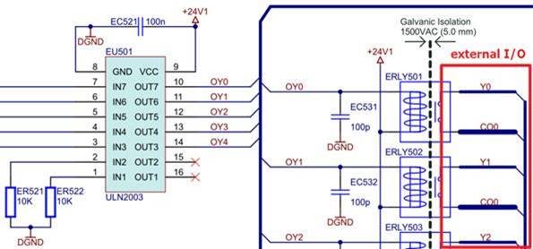
My customer used ULN2003ADR in PLC DO application that drive relays, the circuit as below.

It is the customer's standard circuit and implement on many projects, customer sometime receive returned failure equipments from their end customer and found ULN2003ADR got damaged.

Actually, the failure rate is not large. Customer would like to know is there any protection circuit can be added to get their product more robust.

Dose team have such experience and can provide any recommendation.

Thanks very much.

Vincent Chen

  • Hi Vincent, 

    Thanks for reaching out on E2E!

    To get a better understanding of the system conditions, can you answer the following questions:

    • What are your operating conditions? (Load current, operating voltage, are all the channels turned on at the same time?)
    • When does the device fail? During startup? After field tests? After long duration of extended use? 
    • The report shows that pins 7 and 8 saw EOS damage. What is the load connected to pin 7 / OUT7? 
    • Are you PWMing or toggling the input pins at a certain frequency?

    As an initial assessment, here are some tests you can try:

    • Can you include a 0.1uF from pin 7 to GND?
    • Are you using long inductive cables? Can you try reducing the cable length?
    • Does the input voltage spike during operation? If so, I recommend including TVS to prevent over-voltage conditions?

    Thanks,

    Arthur Huang


    To find the latest information on Power Switches, visit www.ti.com/powerswitch

  • Hi Arthur,

    Thanks a lot for your commend, please find below for customer's feedback.

    What are your operating conditions? (Load current, operating voltage, are all the channels turned on at the same time?)

    >>Load current: Max 8mA/channel.

    >>operating voltage: 24VDC

    >> are all the channels turned on at the same time: Yes, that’s possible.

    When does the device fail? During startup? After field tests? After long duration of extended use?

    >>After long duration of extended use

    The report shows that pins 7 and 8 saw EOS damage. What is the load connected to pin 7 / OUT7?

    >>OUT7: Relay with coil resistance about 3Kohm. Pin7 : Control signal from MCU.

    Are you PWMing or toggling the input pins at a certain frequency?

    >>The frequency of signal under 10Hz, because relay cannot switching too fast.

    Thank you.

    Vincent

  • Hi Vincent, 

    Thanks for the additional details, at an initial glance I don't see anything wrong with the configuration. As mentioned before, are you using long inductive cables or are you seeing large amounts of inductive kickback during operation? Another suggestion would be to add an external flyback diode to work in addition to the internal one, if the inductive ringing is large. 

    You could also parallel channel 7 with one of your unused channels (1 or 2) for additional robustness. 

    Can the customer attach any oscilloscope shots during operation? Any waveforms showing the current spike during operation would be appreciated.

    Thanks,

    Arthur Huang

  • Hi Arthur,

    Actually, I also suspected the kickback spike voltage since there is an inductive load of a relay. And asked customer to add a external diode connected to +24V1.

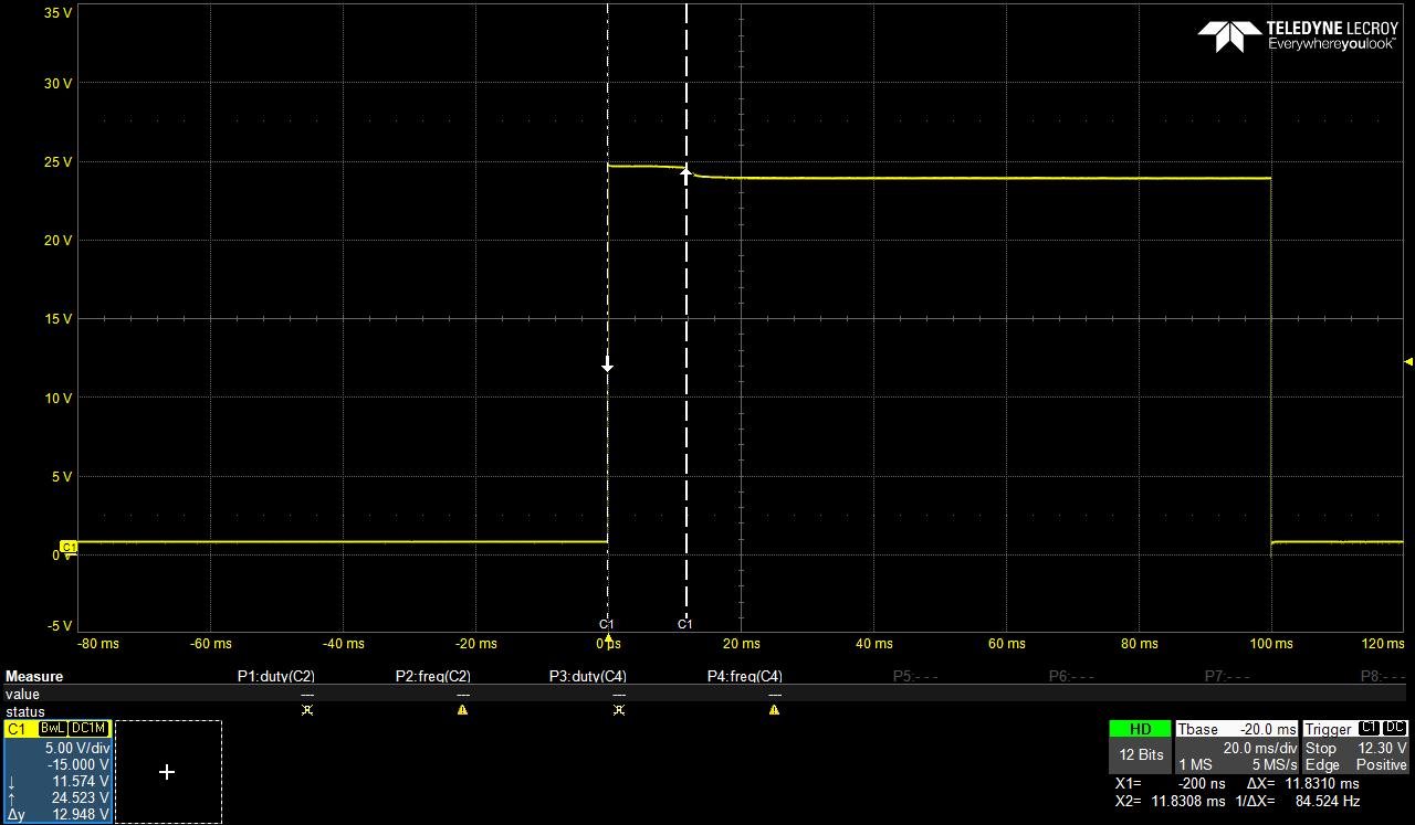
    Output pin waveform of original circuit, it did have a voltage spike and it is clamped at 24V+Vf. We don't know how large the spike is but the spike duration seems quite long, about 12mS.

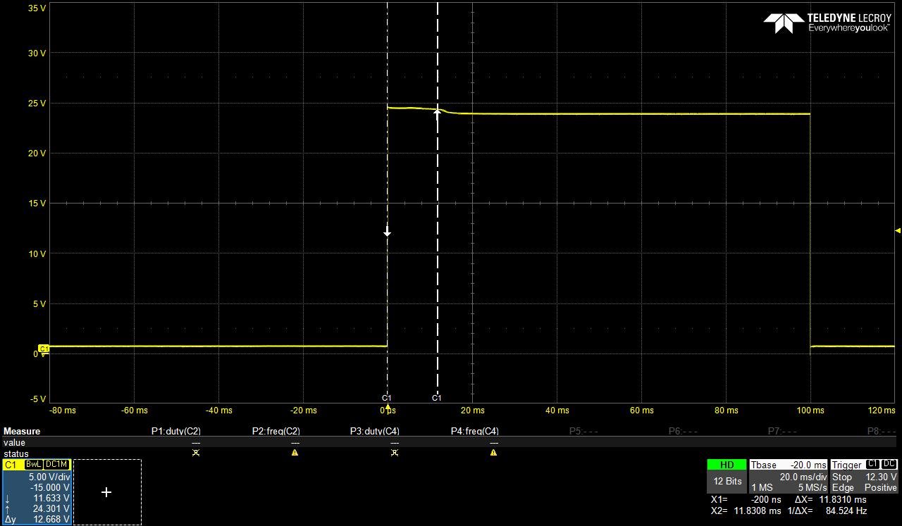
    Waveform with an external flyback diode. It seems the Vf of the external diode is lower than internal diode due to the clamped voltage is a bit lower. I thought most spike energy want through the external diode.

    Customer cannot reproduce the damaged phenomenon in Lab, so we don't know an external diode is a workable solution or not. Based on your experience, add an external diode can have customer's product more robust or not? If this is a case, how to choose a suitable diode? 

    Thanks very much.

    Vincent Chen

  • Hi Vincent, 

    Yes, the majority of the inductive kickback should go through the external diode. We don't have a solution guide for selection the appropriate diode, but as long as the diode drop allows for the current to pass through the external diode, you should be good.

    In general, I find it unusual that the ULN2003A can be damaged only at 24V. Also, it seems like the customer cannot replicate the issue in the lab. Is there some special condition that causes the device to fail in the field vs their lab test? Again, maybe long inductive cables or operating conditions?

    Thanks,

    Arthur Huang