This thread has been locked.

If you have a related question, please click the "Ask a related question" button in the top right corner. The newly created question will be automatically linked to this question.

MOSFET driver for BMS 30S..32S Li Ion (130-150V)

Other Parts Discussed in Thread: BQ76PL536, BQ76200

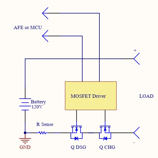
Hello friends. Please advise MOSFET driver for use with BMS 30S..32S Li Ion. A low-side driver is desirable, with two inputs/outputs to control charging and charging MOSFETs. If the driver will have a enable input, it will be just fine.

  • Hi Alexey,

    Thanks for reaching out to the High Power Drivers team, my name is Mamadou Diallo, I am the AE supporting low-side drivers.

    UCC27524 (5A dual channel, with enable pins) may be a good starting point.

    Additionally, copied below is the link to our dual low-side drivers portfolio where you may find alternatives. 

    Please let us know if you have further questions or press the "green button" if this addressed your inquiry.

    Thanks.

    Regards,

    -Mamadou

  • Hi Mamadou, thanks for the reply. Our device will be based on TI bq76pl536 chip (76PL536 EVM as a basis). As the main processor we will use STM32 or TI MSP430 - it is a Board of cell control and protection control.

    For the power Board requirements are approximately as follows: 200A Discharge/50A Charge, 20xDSG - 20xCHG Mosfets in series configuration (IRFB 4115 possible choice), will probably be more powerful transistors in a smaller number. Battery operating voltage up to 130..150 volts (30..32S Li Ion). Input threshold desirable CMOS. it is also desirable to have Enable Pin, to be able to block both transistor control outputs at the same time. Driver power 5..12 volts.

    I had experience of using the high side driver BQ76200 in other BMS, but according to the Datasheet, its voltage is limited to the level of 100V. Therefore, to simplify the scheme and expand the choice of drivers, it was decided to use the low side mosfet driver.
  • Hi Alexey,

    Thanks for the additional information.

    It sounds like you plan on using the low-side driver in a high-side configuration, if so, this device along with a discrete level-shifter and isolated bias may help control the required fast turn-on/off of the battery protection circuitry. The tech note below discusses how to implement this topology:

    Please let us know if you have further questions or click the green button if this helped address your inquiry.

    Regards,

    -Mamadou

  • Hello Mamadou, thank you for the answer. Please do not close the topic, I will read the document and ask you more precise questions.
  • Hi Alexey,

    Feel free to post on this thread as you read through the document and more questions arise, the thread will re-open automatically.

    Regards,

    -Mamadou
  • Hi Mamadou, I read your article about replacing relays with transistors, good article, thank you. In my case, the situation is somewhat different. Transistors will be used on the low side.

    Here is a simplified block diagram.

    And I'm worried about how I better supply power to the driver, and whether the driver will burn from the high voltage on the Mosfets.

  • Hi Alexey,

    Thanks for your feedback and follow up questions.

    This topology would not work due to the fact that load negative terminal may swing well below GND level(commonly occurring in battery packs systems) when CHG is not being pulled high. This could forward bias the internal body diode of the charging channel driver's output stage.
    Adding a discrete P-channel FET to the to CHG path may help prevent the voltage from LOAD(-) from reaching the driver's output stage.
    Section 7.3.1.3.1 of the document below discusses this:
    www.ti.com/.../bq76920.pdf

    I am going to close the thread but please feel free to further post if you have additional questions and it will automatically re-open the thread again.

    Thanks.

    Regards,

    -Mamadou