This thread has been locked.

If you have a related question, please click the "Ask a related question" button in the top right corner. The newly created question will be automatically linked to this question.

LM317: Using positive LDO for negative voltage

Part Number: LM317
Other Parts Discussed in Thread: LM337, TPS7A33

My application is to post regulate an SMPS output with +5V and -5V.

Is it ok to use LM317 where the input is floating, and the output is nailed to ground. A picture will make this clear. 

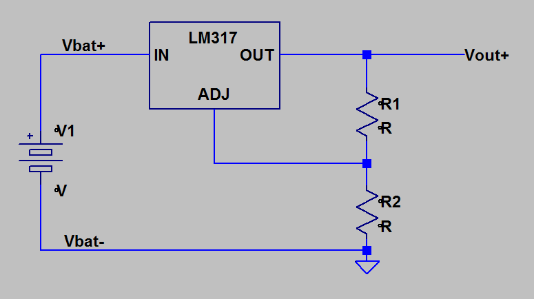
This is the normal way to connect up the LDO. Vbat- connects to ground and Vbat+ connects to LM317 input. Vout+ is a positive voltage relative to ground. Okay.

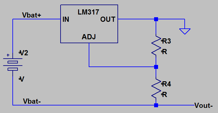
Now consider this alternative. The input battery is floating, so just connect the LM317.OUT to GND and use the Vbat- as the output. I think this works, just not sure how good.

In my case, Vbat is the floating output of an SMPS supply.

I am considering this because the negative LDO LM337, has crummy frequency response as compared with the LM317.

Any thoughts?

gene

  • Here is the normally configured LM317

  • Hi Gene,

    Are you attempting to convert a positive input voltage to a negative output voltage? Linear regulators are designed to convert a positive input voltage to a lower positive input voltage, or to convert a negative input voltage to higher (less negative) negative output voltage. Although the LM317 could be used in the circuit shown by the first picture to achieve a negative output voltage, it was not characterized or tested for operation this type of application. As such, the performance specifications will likely differ from those listed in the datasheet. 

    If you are attempting to convert a negative input voltage, LM317 can be used with the following circuit to regulate a negative output voltage. The output voltage is calculated with the following equation:

    Vout = -Vref * (1 + R2/R1) - Iadj * R2

    I would also like to point out that the TPS7A33 is a good alternative to the LM337 if you do not require more than 1 A output current. It is a negative output ultra low noise LDO with high power supply rejection (PSRR) making it very effective as a post regulator. 

    Thanks,

    Gerard

  • Gerard,

    Nope - not trying to convert a negative voltage to positive. I'm regulating a floating input voltage, and tying the positive output to ground.

    If you imagine the regulator as a black box, input, output and common. Connect a battery so that Vbat+ goes to the input and Vbat- goes to the common. The regulated voltage appears between output and common - such that the output is more positive than the common, yes?. For the sake of argument, Vbat+ - Vbat- = +10V, it's a 10 volt battery. The regulator is configured for Vout - Vcommon = +5V.

    So far, no ground connection. The regulator doesn't have any notion of ground - it just does its job and maintains some positive voltage between output and common. Now, tie the output to ground and what happens? Well, if the more positive output is at zero potential (ground), the the common is regulated at a negative voltage. In my example, Vcommon should now be regulated to -5V.

    That's what my circuit is supposed to do. And now i wonder if there's anything wrong doing it this way? I'll bet that debugging it will unusual since things float - so maybe a differential measurement is needed? Not quite sure about that.

    If this explanation makes sense, then i wonder if this is really a bad way to do things or not? As I wrote, the LM337 noise and ripple specs are not as good as the LM317.
  • Hi Gene,

    Thanks for explaining in more detail. I understand what you are trying to achieve assuming common refers to the ADJ pin of the LM317 and LM337 regulators, and instead of 5 V, the difference between OUT and ADJ is forced to Vref = 1.25 V (typical). If OUT is grounded, the desired negative voltage can be achieved by selecting R3 and R4 such that:

    Vout- = - Vref * (1 + R4/R3) - Iadj * R4

    To my knowledge of your application, I do not believe there is anything wrong with operating the regulator in this configuration since, as you have pointed out, there is no ground reference pin. Furthermore, if the battery is 10 V, there is no risk of exceeding the absolute maximum recommended input-output differential voltage (40 V for the LM317) when grounding the output. However, note that the minimum recommended output voltage (voltage at the OUT pin) is 1.25 V. Grounding the OUT pin may result in regulation performance differing from the datasheet specifications.

    I would also like to point out that this circuit requires (Vbat+ - Vbat-) + Vout- > 0 V. This will ensure that IN of the regulator sees a higher voltage than OUT, allowing it to adjust the current through the pass transistor from IN to OUT to maintain 1.25 V between OUT and ADJ.

    Another thing to keep in mind is that a lot of power may be dissipated in the pass transistor depending on the load current and Vout-. The junction temperature of the regulator can be approximated with the junction-to-ambient thermal resistance (Rja) specified in the datasheet. This should be kept at or below 125 C:

    Tj = Ta + Pd * Rja <= 125 C

    Where Ta is the ambient operating temperature and Pd is the power dissipated in the pass transistor calculated as:

    Pd = (VIN - VOUT) * Iout = VIN * Iout = [(Vbat+ - Vbat-) + Vout-] * Iout since OUT is connected to ground.

    It is possible to reduce Rja by using an external heatsink or by adding copper on the PCB local to the LDO to act as a heatsink.

    Thanks,
    Gerard