This thread has been locked.

If you have a related question, please click the "Ask a related question" button in the top right corner. The newly created question will be automatically linked to this question.

TPS2121: Dose it break by reversing battery?

Guru 11255 points
Part Number: TPS2121

Hi team.

I'd like to get your advice in our situation.

I am thinking the battery circuit using TPS2121.

In one case,It is conceivable that the battery is reversely connected.

In this case, the negative power enters the device.

Is there any problem? and is the device broken?

I think it is NG, because the device can not enter the negative power.

(According the datasheet at p.6)

I am happy, if it dose not break and protection works.

Sincerely.

Kengo. 

  • Hi Kengo,

    Thanks for reaching out on E2E!

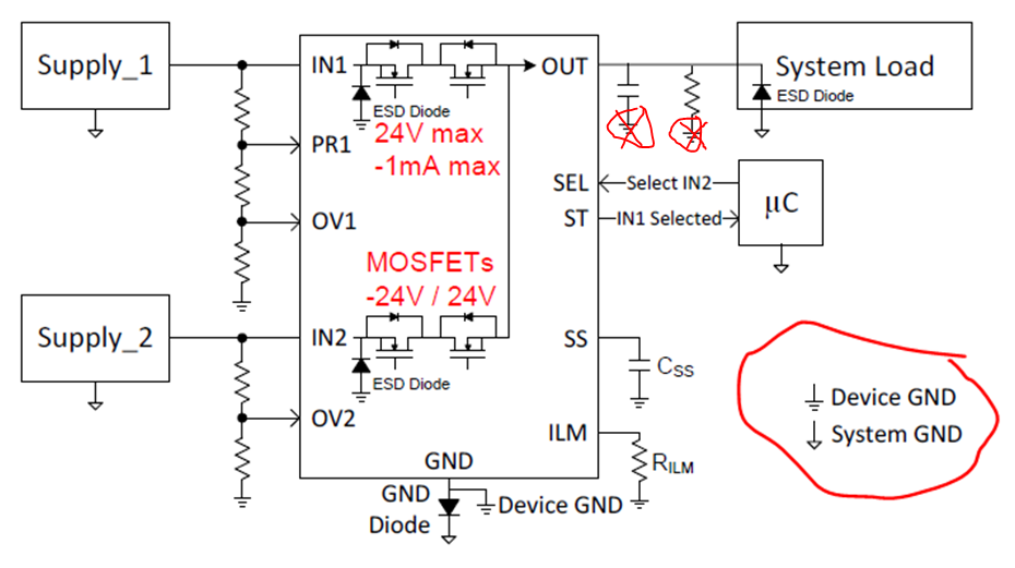
    Reverse voltage protection can be enabled on our device by connecting an external diode from the GND pin of the device to system GND. As shown below, all the IC parameters are connected to Device GND, instead of System GND:

    • During normal operation, all of the control pins (PR1, CP2, OVx) are referenced to the IC’s GND pin. If a diode is connected to enable RVP, all of the control pins need to be connected to device GND instead of system GND.


    • Furthermore, the thresholds need to be recalculated based on the voltage drop across the diode. Since the diode can shift the thresholds up by 0.4-0.7V (diode drop), your control pin thresholds will be shifted up as well. Therefore, since supply_1 and supply_2 are in respect to system GND, you’ll have to subtract the diode drop before determining the thresholds:
      • Example: (VOV1  - VDIODE) * (RBOT ) / (RBOT+RMID+RTOP) = 1.06V
    • The ST, SS, and ILM thresholds will also be increased by VDIODE. This may adjust your thresholds as well, depending on your configuration.


    • The load capacitor and output resistance were labeled incorrectly in the diagram, I suggest connecting them to System GND instead of device GND. This way, if the device experiences a large inrush current event, the current charging the output load won’t flow through the device.

    Let me know if you have any questions!

    Thanks,

    Arthur Huang

  • Hi Arthur.
    Thank you for your reply.

    I understood almost.
    However, why should I adjust the ST,SS,ILIM ?
    I think they are based on the device GND.

    Sincerely.
    Kengo.
  • Hi Kengo, 

    I'm not sure I understand the question correctly. The ST, SS, and ILM pins should be referenced to device GND instead of System GND because this will make it easier to calculate the voltages necessary on each pin without including the diode drop. \

    Thanks,

    Arthur Huang

  • Hi Arthur.
    Thank you for your reply.
    I understood that the ST,SS,and ILIM connecting to device GND, the voltage drop due to the diode can be neglected.

    Sincerely.
    Kengo.