This thread has been locked.

If you have a related question, please click the "Ask a related question" button in the top right corner. The newly created question will be automatically linked to this question.

LP5912: Schematic review please

Part Number: LP5912

hello, i just started to grow interest in electronic and trying to design a pcb using LP5912-3.3DRVR as my 3.3v LDO. sorry if my questions might be very simple but i lack knowledge in some areas. i have 3 diagrams please take a look at them.

1-in this figure 1 im trying to feed that microcontroller on the right and the datasheet of it advises for a 10uF cap to be placed between vcc and gnd pins. LP5912 will be placed next to that microcontroller so can they share that 10uF (C3) cap or i should add another one?

2-if you noticed i added external mechanical switch to vcc line(from BAT) which goes to IN of LP5912 because i also want to cut power of that voltage divider. i seen in the datasheep that PG pin can be left floating or connected to ground but couldnt find anything about EN pin. most other LDOs tell you that you can connect it directly to IN side if you dont need EN function. so does that also looks correct? 

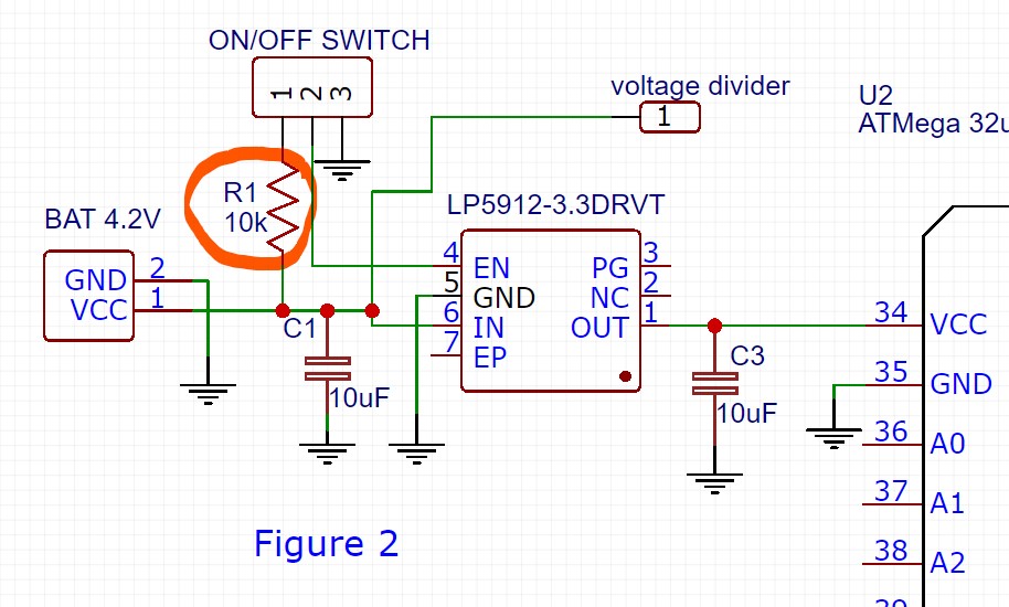
3- if i ever decide to use EN function does that look ok? i have seen some other examples using a resistor(10k- 100k) between the IN and EN pin do i need it here or should i remove it?

4- this is my second application and the chip that im trying to feed suggest to use 3rd cap(C3) in range of 4.7uF-10uF in addition to 1nF(C4) and 10nF(C5). i have noticed in the datasheet maximum output capacitance should be 10uF. so in this application can i keep it as it is or should i reduce that C3 to 4.7 uF?

thank you for assistance have a nice day.

  • Hi Kamen,

    As long as the microcontroller is physically close to the LDO output, a single shared output capacitor may be okay; however, we always recommend prototyping so that you can understand the performance that you can expect in your specific application.  From the LP5912 perspective there is no issue with this.  Keep in mind that should you find that the 10 uF shared capacitor is not enough, LP5912 has a maximum capacitance of 10 uF on the output so you are limited on how much you can increase the output capacitor.

    The enable pin for LP5912 can also be tied to Vin.

    In Figure 2 there is no issue having the resistor; however, it is not strictly required.  You will notice that we did not have this resistor on our LP5912DRV18EVM.

    For your last question you will need to look into the derating of the capacitors that you select.  You should be able to find derating curves from the capacitor manufacturer's website.  Keep in mind that there is a difference between the nominal capacitor value and the capacitance that you will have on your board.  Check out Chapter 2 of our LDO Basics E-Book for more information on capacitor vs capacitance.

    www.ti.com/.../slyy151.pdf

    Very Respectfully,

    Ryan

  • thank you for the quick reply i will look into that last matter. have a good day
  • im not sure if i got it right but to my understanding for example X7R ceramic caps have %10 tolerance in capacitance. so if 10uF cap goes -%10 it will be able to compensate for the other two 1nF and 10nF caps. But if it goes +%10 then its no good :) the way i see it i guess 4.7uF cap instead of 10uF will be the safe bet.