This thread has been locked.

If you have a related question, please click the "Ask a related question" button in the top right corner. The newly created question will be automatically linked to this question.

UCC28180: PFC MOSFET Failure with UCC28180D

Part Number: UCC28180

Currently we are facing the failure of the PFC MOSFETs in out product and the PFC is controlled by UCC28180D. More details are provided below…

 We understood PFC control IC as one of the main cause, Need your support here…

Details:

Design: 230V AC to 650V DC BOOST PFC Converter

Failure Happens during the Step load of 3kW at the output… (Load Transient)

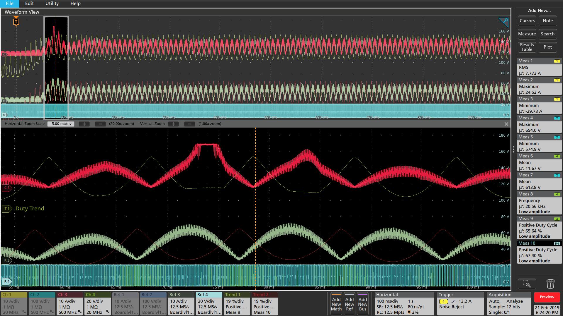
Waveform-1 during the MOSFET failure: (Yellow: Input Current, Blue: DC BUS/output voltage, Red: Inductor Current, green: MOSFET Duty)


We did more experiments to understand what is happening to the control… we had some observations with PFC current sense changes…PFC Current sense in the Design is 7.5mohm

 PFC _with Load Step_2kW_with15mohm

PFC _with Load Step_2kW_with7.5mohm

Found that duty is clamped at the peak of input with higher causing current increase between 60 to 120 deg. and current shape is becoming non-sinusoidal.. below is the comparison waveform with 15moh and 7.5mohm Current sense


 Kindly help to understand this better and resolve the issue ASAP.

Regards

Siva Tella


  • Hi, Siva

    The duty cycle is clamped at peak input voltage is because ICOMP reached 6V which is clamped voltage level of ICOMP.

    The control algorithm of UCC28180 is based on universal input range, the current sensing resistor should be calculated with 85Vac otherwise it is possible to make ICOMP reach the internal upper clamp threshold, i.e 6V, current loop becomes an open loop, a fixed PWM duty is generated at AC peak, which causes AC current spike as the plots shows.

    In order to resolve this issue, the best way is to reduce the current sensing resistor although it causes peak current limit increases. Another way is to increase the bulk voltage extremely, but I assume it is not an acceptable method from customer’s standpoint.  

    The calculated Rsense may too large if the selected minimum input voltage is higher than 85Vac.

    Regards,

    Yunsheng

  • Hi Yunsheng

    Thank you for the replay

    we have ~170V AC as minimum input voltage, and 3kW should be the power limit what we are looking for.
    if we increase the current sense resistor, Will it be possible to limit the power 3kW@170V with this IC.

    As per the calculation we got the current sense ~7.5mohm, is this is not OK....

    Does the SOC (Soft Over Current) and PCL (Peak Current Limit) not limit the POWER?, when these will come into act.
    You have mentioned another way to increase is the bulk voltage...is this the output voltage you are referring to or any other voltage?

    Regards
    Siva
  • Hi Yunsheng,

    If we reduce the current sense resistor, it will allow higher current during dynamic load change in the output; which may cause input Fuse to fail or input MCB to trip? How to handle that situation?

    Thanks and Regards

    Goutam

  • Hi, Goutam 

    I assume you and Siva are working on the same project with UCC28180. So I reply your questions together:

    1. The SOC is triggered if ISENSE <-0.288V and PCL is triggered if ISENSE<-0.4V

    2. If you increase the current sense resistor, it is possible to limit the power 3kW@170V with this IC. But you may observe distortion of inductor current because ICOMP is saturated and clamp to 6V. For Power limit and shape of inductor current, you may not be able to get satisfactory results at the same time. And it can be proved by your result: if current sense resistor=7.5mohm, you can get better inductor current waveform, but the SOC threshold at 170Vac would be >3kW.

    3. So recommend to select current sense resistor to 7.5ohm, and add external over current protection circuit.

    4. For voltage gap between peak input voltage and output voltage of PFC, I recommended 20V.

    5. have you see failure of input fuse when reducing current sense resistor? speed up voltage loop response a litter bit can help to handle output load transient.

    BR,

    Yunsheng 

  • Hello Yunsheng

    we are still facing the issue...

    Our Current sense is 7.5m ohm, still we are facing the same issue of ICOMP clamping to 6V and Duty clamping during the 3kW load Transient.

    Our minimum DCus b/Bulk voltage is 450V, if considering maximum of 270V AC also, we have 70V voltage GAP between peak of input voltage and bulk voltage..

    Need further support here...

    suggest if you share your mail ID.. we can have one to one discussion with more details

    Regards
    Siva
  • Hi, Siva

    my mail ID is yunsheng-qu@ti.com.

    let's move to Email, let me close this forum. 

    Yunsheng