This thread has been locked.

If you have a related question, please click the "Ask a related question" button in the top right corner. The newly created question will be automatically linked to this question.

UCC28070: PMP4311

Part Number: UCC28070

Hi team,

I have below questions about PMP4311 reference design, appreciate your explanation.

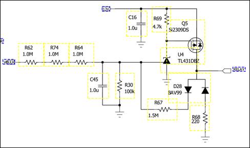
1. Working principles of R67, R68 and D28

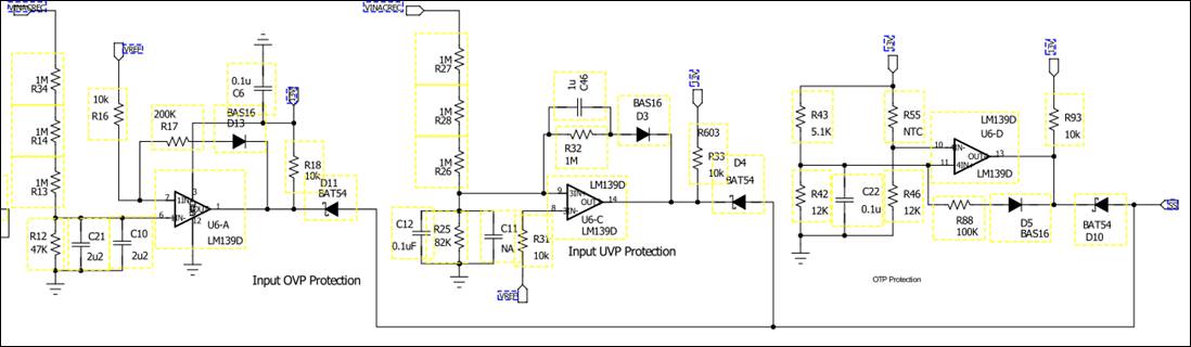
2. Working principles of LM139D and BAT54

3. Working principles of Q2

Thanks,

Miranda

  • Hello Miranda,
    (1) This is the relay drive that when powered on will disable the input surge current limit on the pfc.
    The relay is first powered on when there is sufficient voltage on high voltage output to generate 2.5V on U4
    At this time the input surge has passed so it is safe to power up the pfc.
    Once power is applied to the relay coil , the 13V coil voltage applies power to U4 adjust pin through D28 and R67
    This ensures the relay remains powered up during any sags and dips in the pfc output.
    R67 is used to dissipate any stored energy in the coil when the system is powered off and prevent any possible inductive spike from damaging U4
    (2) The BAT54 diodes are used as discrete OR circuits that will pull the soft start (SS) pin of the UCC28070 low if either an overvoltage or over temperature condition is activated. The LM 139 is set up as a comparator with a fixed reference input and a variable input. When the variable input exceeds either of the fixed reference thresholds then the system is shut down by pulling SS low.
    (3) This circuit does not appear to have worked since it is disabled. It looks like its intent was to limit the power capability of the pfc .
    Enabling the system limits the power to one value and disabling gives another power limit.

    Regards
    John
  • Hi Miranda,

    Thank you for your interest in PMP4311, please find my comments below:

    1. The Relay circuit is to disable the inrush limiting circuit once the Vout is high. The purpose is to save the power losses across the RT4 and RT5 resistors once steady state is achieved. 

    2.  LM139D and BAT54 circuit looks at the current sense for both the phases and monitors the line current scaled down by the current transformer. These are fed through the comparator circuit to generate EN signal. at Light load condition, the CSB would be low and this will pull EN low thus disabling PhaseB.

    3. Q2 and R7 are not fitted.

    Regards,

    Sonal