This thread has been locked.

If you have a related question, please click the "Ask a related question" button in the top right corner. The newly created question will be automatically linked to this question.

UCC28070: UCC28070 how to measure voltage loop bode plot

Part Number: UCC28070

Hi team,

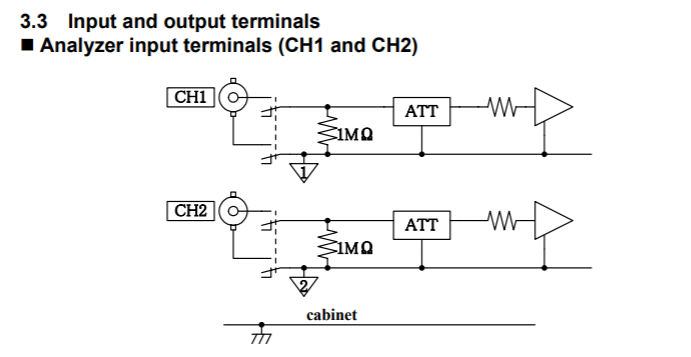
My customer is using UCC28070 in their design and want to measure the voltage loop bode plot, but their frequency analyzer (FRA5087) can only support inputs upto 250Vrms. 

Is there anyway to measure the HV voltage loop like adding a buffer or amplifier?

Many thanks.

Best Regards,

Wei-Hao

  • Hello Wei-Hao,

    I am not familiar with the FRA5087 so I looked at the instruction manual for this equipment and I understand the problem is this:

    The cabinet is tied to safety earth and CH2 /CH1 can be at perhaps 264Vac with respect to earth if used with a pfc circuit.
    So this will exceed the rating of the instrument.

    But if you use an isolated source for the AC input to the pfc (from an isolation transformer or isolated lab supply) then CH1 and CH2 are floating  with regards to the cabinet.

    I recommend that you :

    (1) Place the signal injection resistor on the low voltage side of the resistive divider on the VSENSE line
    This will lower  CH1,CH2 voltage with respect to the cabinet.

    (2) Use an isolated source for the AC power to the pfc

    (3) Double check these connections before connecting the instrumentation.

    Do you think this will work ?

    Regards

    John

  • Hello Wei-Hao,
    I am going to close this post since there has been no new info in over a week and I believe the issue has been amswered.
    Please open a new post if you have further issues.
    Regards
    John
  • Thanks for your explanation John.

    Best Regards,
    Wei-Hao