This thread has been locked.

If you have a related question, please click the "Ask a related question" button in the top right corner. The newly created question will be automatically linked to this question.

Li-ion 3s Battery Charger with Load Sharing

Other Parts Discussed in Thread: BQ25713, TPA3128D2, TPS62125

Hi, I am requesting help to create a battery charger and load sharing circuit with the following specifications:

  • 3s Lithium Ion battery
  • 12 V at 2 Amps to power TPA3128D2 Class-D Amplifier (this is for max volume. Possible to lower the voltage/current to accommodate design constraints)
  • 2.7 V at 50 mA, low noise to power STM32F4 microcontroller as well as external DAC and analog circuitry
  • Charging done via USB Micro-B port with USB 2.0 (5 V at 500 mA or 1.5 A)

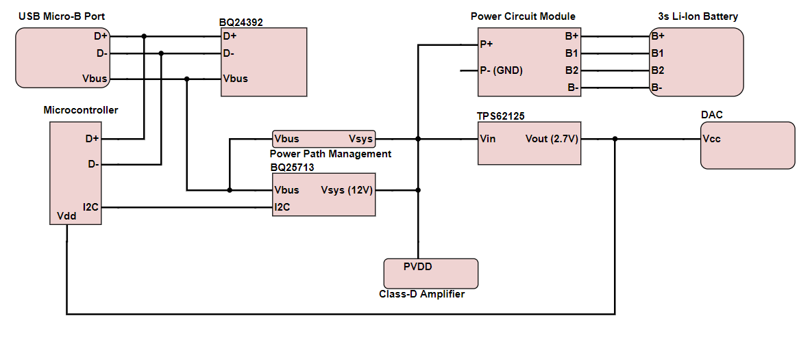
I am currently considering this design:

  • Power Circuit Module to handle battery charging and balancing.
  • BQ25713 to handle the load sharing/power path management as well as 12 V boost converter
  • TPS62125 to output the 2.7 V from the BQ25713 power path
  • BQ24392 to handle USB charge detection/enumeration

I would appreciate any help on confirming or denying the viability of this design as well as any suggestions on any improvements that can be made for simplicity.

Edit: Simple block diagram for clarity

  • Hey Daniel,

    I think this is a good implementation for what you are trying to do.

    However, I do have two comments and questions:
    1) Where is the boost converter sitting here?

    2) What is the VBUS ---- VSYS block doing there?

    3) One thing we want to make clear about these chargers is the voltages that are produced and the limitations that are presented during operation. For one, the system voltage and the battery voltage will track down to a certain discharge level as long as an adapter is present. This means that when an adapter is present, the system voltage will not go any lower than the "VSYSMIN" threshold. However, in the battery only configuration, the voltage on the VSYS pin of the charger will follow the battery by an IR drop. Another thing to keep in mind is regulation of the system voltage when the input is overloaded. If this occurs, which will likely happen due to the limitations of the USB port power you mentioned, the system voltage will also track below the battery voltage.

    If you have already considered this, then you should be okay barring that VBUS-VSYS block and the placement of the boost converter.


    Regards,
    Joel H
  • Joel,

    Thank you for your response.

    1) I was confused on how the BQ25713 operates. I assumed that there was an internal buck/boost converter to regulate Vsys, but I see now that Vsys is the battery voltage and there is just Vmin protection. The boost converter I mentioned was originally to supply the Class-D Amplifier, TPA3128D2, with a regulated voltage, but the TPA3128D2 seems to have its own internal regulators. Would It be OK then if I just supplied the TPA3128D2 with the battery voltage (7.5 - 12.6 V) without a regulator?

    2) The VBUS --- VSYS block was my poor attempt at modeling the power path management that the BQ25713 does. I know it uses power MOSFETs along with outputs from the IC to regulate system voltage.

    3) Could you elaborate a bit more on two things here. First, with a battery only config, the VSYS pin will follow the battery by an IR drop. Second, when talking about the regulation of the system voltage, what do you mean by the input being overloaded?

    Overall, the TPA3128D2 and TPS62125 has minimum supply voltage of 4.5V and 3V respectively. The battery has minimum voltage range at 7.5V. So I assume that if I set the Vmin Active Protection at 5V everything should work fine.

  • Hey Daniel,

    To 1) I should have been more clear. the buck-boost charger does regulate VSYS, but to two values, and only when the adapter is present. If the battery voltage is below a certain threshold, the charger will regulate VSYS to a voltage called VSYSMIN. VSYSMIN is that threshold. Now, if the battery is above this threshold, the regulation point for VSYS is VSRN + 160mV. There are a couple of other conditions which I described in (3). And you can use either the battery voltage or the system voltage. The battery voltage and VSYS are only separated by the external BATFET PMOS. Using VSYS will give you the power management feature, allowing you to use available input power to drive your system.

    To 2) Correct.

    To 3) When there is only a battery present, the converter does not operate normally. If it does operate (which is called OTG mode), it certainly does not regulate VSYS. In this scenario, that same PMOS BATFET is turned fully on, so the voltage VSYS = battery voltage - Load current x Rdson_PMOS.

    There is also a scenario when the input is overloaded for any reason. We have two loops in the charger that allow it to regulate the input in some way, either by regulated a programmed current limit or by regulating a default input voltage. In these scenario, hitting these loops will forced the charger to first, attempt to decrease the charge current to maintain the system voltage, and second if necessary force the BATFET to conduct in the forward direction to help supplement the system load. In this second condition, the system voltage can fall to below the battery voltage.


    As far as the Vmin Active Protection, this is mostly useful for high transient peak currents that don't last too long when you are in the battery only operation. It was developed as a requirement for Intel platforms to help keep the system voltage up during a high peak load. However, if an adapter is present on the charger, you can program a VSYSMIN voltage such that the charger always regulates to this voltage (unless you hit a condition in (3)).


    Regards,
    Joel H