This thread has been locked.

If you have a related question, please click the "Ask a related question" button in the top right corner. The newly created question will be automatically linked to this question.

TPS61020: About the operation when the output capacitor is small

Part Number: TPS61020

Hi teams

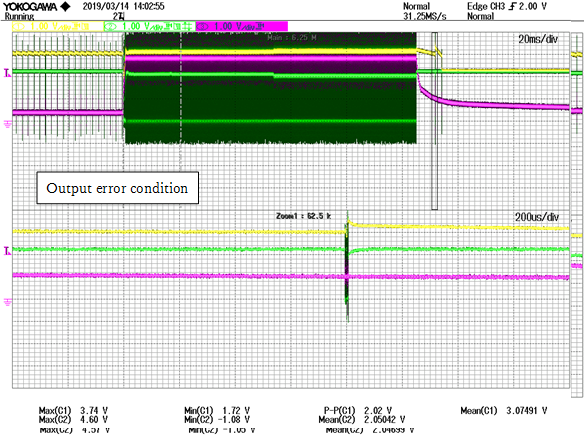
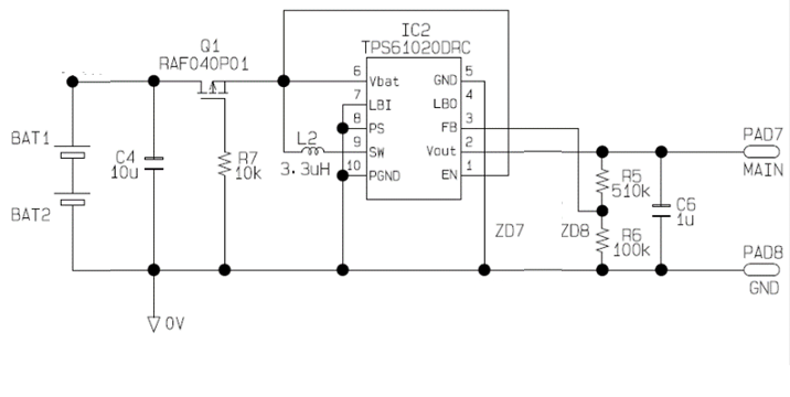
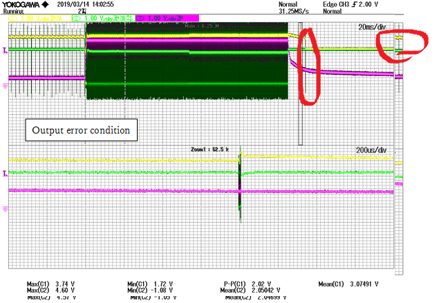
The output voltage of TPS61020 becomes the same potential as the input voltage.
Although the set voltage is set to 3.05 V and the enable pin is pulled up to the
power supply voltage, the input voltage is output as it is without being boosted.
The voltage at the FB pin is 0.35V, so it should work, but it does not work.

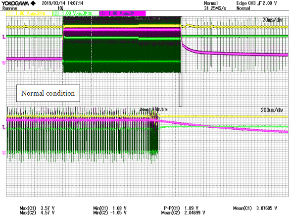
  Please let me know what is the reason for this. Best regards Hayashi

  • Hi Hayashi:
    May you share something more detail? What't the load condition? Is it loading during startup?
  • Minqiu san

    Thank you for your support.
    This event is a rare event and occurs when changing the load on the output from 1mA to 20mA and then 1mA by inputting 2.2V with the regulated power supply.
    At the moment when the load is lightened, it seems that boost operation is being performed once, but the voltage will drop immediately. Is it due to the capacity of the output capacitor?

    Best regards.
    Hayashi
  • Hi Hayashi:
    If an output overload occurs during normal operation, the converter returns to precharge, preventing an input bus overload. If output voltage decreases below the input voltage by more than 100 mV, the converter returns to the first start-up phase which is precharge. This restarts the start-up sequence again and the original entry and exit requirements apply.

    May you share your schematic for me? And please try if it could recover if removed the load after failed.
    And what's the input power supply? Is it stable and work well all time?
  • Minqiu san

    In this case, it may occur when the load of 20mA is changed to the load of 1mA. So I think that the cause of this time is not overload protection.

    I will attach a schematic. In this circuit, the capacitance of the capacitor can not increase the input and output capacitance per customer requirement. I think the output capacitor is the cause of the problem, but I do not know the reason.

    The power supply used in the graph attached yesterday used a stabilized power supply. In fact, we plan to use batteries.

    Best regards
    Hayashi

  • Hi Hayashi:
    Sorry that I misunderstand the load transient.
    What's the signal in yellow? Is it the voltage of the BAT pin? And could you measure the current of the inductance?
  • Minqiu san

    I will answer your question.

    The yellow signal is the output voltage. The set voltage is 3.05V. The voltage at the BAT pin is 2.2 V (in this graph, a regulated power supply is used).
    Inductance current can not be measured immediately.

    Best regards
    Hayashi
  • Hi Hayashi:
    I'm sorry that I'm not familiar with this kind of scope. What's the pink signal?
  • Minqiu san

    Thank you for your timely support.
    I will answer your question.

    The pink line is the main side power supply.
    I don't think it is related to this phenomenon, so please ignore it.

    Best regards
    Hayashi
  • Hi Hayashi:
    Now, let me describe the phenomenon in my word:
    The circuit boost 2.2V from stable power supply to 3.05V target Vout. And when the load is changed from 20mA to 1mA, the Output voltage drops a lot, and then equals to the VIN. After about 40ms, the Vout recover to the target value again.
    Am I right?

    Please show the waveform around the Vout drop moment. It seems a spike.
  • 民秋さん

    私はあなたが見ているデータは異なるかもしれないと思います。

    Voutが目標値に戻りません。負荷が20mAから1mAに変化すると、数回スイッチングしますが、VINの電圧になります。

    もう一度データを貼り付けます。

    Best regards
    Hayashi

  • Hi Hayashi:

    Sorry that I'm didn't know Japanese clearly~

    I note the waveform which i'm interested .

  •  Minqiu san

    It seems that the attached data is pasted with some other data.

    I'm sorry but I will paste the data again.

    Best regards
    Hayashi

  • Hi Hayashi:
    May you share the clear waveform about the left red circle I noted. The moment that Vout drops
  • Minqiu san

    l update the data at the moment when the output voltage drops again.
    There is a zoomed-in waveform at the bottom.
    As you can see, the voltage is falling momentarily.

    Best regards
    Hayashi

  • Hi Hayashi:
    I'm sorry but it's still not clear enough.
    Please zoom in with 20us/div or even short to see the SW point operate clearly. And I'm afraid if the sampling rate and record capability is enough for this waveform.
  • Minqiu san

    I'm sorry, but it is difficult to prepare for what you requested.

    As my idea, I think that there may be a case where it can not be driven sufficiently because the output capacitor is small. But I do not know the internal structure. Please let me know anything if there is a possible something mechanism in the current phenomenon.

    Best regards
    Hayashi
  • Hi Hayashi:
    I couldn't re-produce the phenomenon in our lab with Cout=1uF. So the behavior around the voltage drop moment is import for me to try to re-produce.
  • Minqiu san

    Thank you for your support a lot.

    There are one case out of 20 occurs even for my customers.
    Please let me know is it possible to increase the number of parameters for verification?

    In addition, we have re-requested an extension of the falling range we have requested.

    Best regards
    Hayashi
  • Hi Hayashi:
    I have sent an private massage to you. You could contact me with another ways. And I'll close this post firstly.

    Please understand that the operation waveform is important to analysis the circuit behavior. It's better that I could re-produce the issue in my lab.