This thread has been locked.

If you have a related question, please click the "Ask a related question" button in the top right corner. The newly created question will be automatically linked to this question.

TPS730: How to adjust TPS73001 soft start time to a larger value?

Genius 3870 points
Part Number: TPS730

Hi,

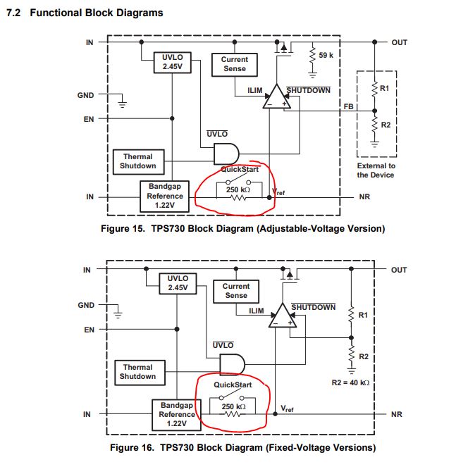
we use TPS73001 for 5V to 2.5V/100mA convertion, C_NR=10nF, feedback resistor R_top=33K, R_bottom=32K, Cff=18pF. As SCH  picture below.

TPS73001 claims fast start up time about 50us, and I guess the actual ramping time is enven less than 50us. That is too fast for our load, which requires 50us to 50ms ramping time .

I found this TI article to be useful. Additional ramping time induces by Cff shoud be t_Cff = 3x33Kohmx18pF = 1.78us. This is rather small and not enough.

Then I realize a LARGER noise reduction cap(C_NR) could possibly extend 73001's ramping time, as long as the RC time on NR pin is large enough. For example, if I change C_NR from 10nF to 1000nF, although this value violates the spec's reuqirement (no more than 100nF), but I guess this will help achieve my goal ? Any method to verufy this usage, such as simulation or math calculation?

Thanks,and have a good weekend.

  • Hi Yi,

    TPS730 was designed for applications requiring a fast ramp rate on the output.  In order to accomplish this, we incorporated a quickstart feature in our design to rapidly charge the NR cap.  While you are correct that on many linear regulators the NR capacitor is used to slow the ramp rate of the internal reference voltage (and therefore the output voltage), this will not work on a regulator with a quickstart function.

    As shown in Figure 19, the slew rate of Vout is largely unchanged while the quickstart circuitry is engaged regardless of your NR capacitor.

    Very Respectfully,

    Ryan

  • Hi Ryan,

    Thanks for patient explain. Yes ,I indeed noticed that TPS73001 has this "quickstart switch" which shorts the 250Kohm resistor inside IC, as well as figure19's small change T_rise between different C_NR.

    So how long is the "Quick Start Switch( in parallel with 250k)"  will keep closed duiring quick start process?  Since datasheet section 8.1.4 mentioned that "The bypass capacitor should be no more than 0.1 μF to ensure that it is fully charged during the quick-start time." ?  I assume that if we use NR cap larger than 0.1uF (or large enough), the RC time (250K*C_NR) will be longer than the time of the quick-start-swtich keeps closed, so there is a chance that we could still slow the ramping slope . 

    If my assumption above is totally wrong, seems that there is no other way to increase the ramping time down to 50us-50ms, or choose other LDOs.....?

    Your insight is appreciated. Thanks again. 

  • Hi Ryan,

    I think about this topic again, and I notcied that TPS73001 has an internal current limit about 400mA (section 7.3.3). I assume this means when over current happening, the device will keep I_out around 400mA until over current condition disappear.

    In our application,  since there is no soft-start funtion for TPS73001, there will be inrush current (I_rush) during Vout ramping. Theoretically I_rush is suppose to be Cout*Vout/dt = 10uF*2.5V/(~10us) = ~2.5A > 400mA, if TPS73001's load are Disabled during start-up. Here Over-Current happens. So TPS73001 will limit the actual inrush current to ~400mA , at the same time Cin might also provide some transient current to help on preventing Vin from dropping down(dip).

    Now, the actual Vout ramping time should be approximately : t_ss' = Cout*Vout/I_limit = 10uF*2.5V/0.4A = 63us.

    This is my personal understanding about TPS73001's behavior for inrush current during start-up, but not very sure.

    Any comments are welcome. Thanks!

  • hi Ryan.
    could you please take a look at my continue analysis above? Thanks!
  • Hi Yi,

    While your understanding of inrush current and current limit are correct, since you require a specified ramp rate for your application, TPS730 or any device with a quickstart circuit will complicate your calculations.  The quickstart circuit will open after the reference voltage is fully charged as shown in Figure 8.

    During this time, the slew rate of the output would be limited by current limit as you mention.  The internal reference will still have the same initial slew rate shown in the Figure 8.

    Please note that TPS730 was designed, characterized, and tested for a quick startup time.  Since you are using this LDO in a different way, it is highly recommended that you prototype your application.

    Very Respectfully,

    Ryan

  • Thanks, Ryan. A last we decide to chage to TPS7A4901 for ensured soft-start function.