This thread has been locked.

If you have a related question, please click the "Ask a related question" button in the top right corner. The newly created question will be automatically linked to this question.

TPS7A7200: TPS7A7200 OCP behavior

Part Number: TPS7A7200
Other Parts Discussed in Thread: TPS7A84A

Hi Expect,

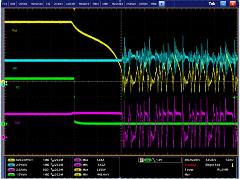
My customer test OCP function on TPS7A7200, they observed strange of the waveform as below, does's it make sense or not? due to mentioned in datasheet ''Do not design any applications to use this current limit function as a part of expected normal operation.'' may i have your comments for this?

Best Regards,

Mark Chen

  • Hi Mark,

    As with most linear regulators, TPS7A7200 is not designed to be operated in current limit.  The rated current for TPS7A7200 for normal operation is 2 A.  If your application requires a higher output current for normal operation, please consider a device that is rated for a higher output current such as TPS7A84A which is rated for normal operation up to 3 A.

    Yes your curve makes sense.  When you reach current limit, the load will begin to pulldown the output voltage because your load is pulling more current out of Vout node than the LDO is sourcing.  This will cause the output capacitors to discharge.  Also keep in mind that the current limit will decrease as the voltage on the output rail decreases.

    The right half of your curve looks like the thermal shutdown with some inductive ringing. 

    Very Respectfully,

    Ryan