This thread has been locked.

If you have a related question, please click the "Ask a related question" button in the top right corner. The newly created question will be automatically linked to this question.

TPS54361: Sometimes TPS54361 is broken when power up.

Part Number: TPS54361

Hi team,

        Customer feedback sometimes TPS54361 is broken when power up, just sometimes. And it was replaced by the new chip TPS54361 in the board, it works well.

We test the broken chip TPS54361, VCC short to SW and GND. We also saw the diode is broken too.

Input is 54.5V form the battery. Output is 5V.

It is hard to re-appear. So it is hard to catch the input signal.  

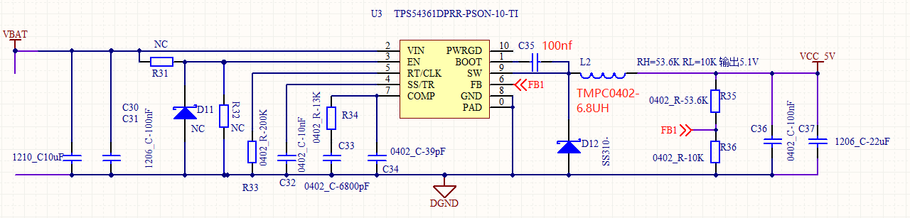
Below is their SCH and layout. Do you have any suggestions? 

Thanks!

  • Hello ,
    How are you protecting the device against any Input voltage transient ? Here are my recommendation based on Schematic you shared :

    1. Add a Bulk cap at the input . Use something like 100uF , 50mohm ESR 100V capacitor for this application . This will dampen the inductive ringing at the input of DC/DC converter
    2. Add another 22uF cap at the output .

    ---Ambreesh
  • Hi Ambreesh,

          Thanks for your help!

    May I know why 100uF , 50mohm ESR can dampen the inductive ringing at the input of DC/DC converter?

    Customer use this SCH for several year so they think the SCH is no problem. They worry the Layout is the roof reason.

    Do you have any suggestions?

    Thanks!

  • Eggsy ,

    Bulk capacitance is required if the Buck converter circuit is not located within approximately 5 cm from the input voltage source. This capacitor provides damping to the resonance associated with parasitic inductance of the supply lines and high-Q ceramics.
    This is high voltage application and any ringing due to parasitic inductance on input trace can lead to failure .
    Share the Gerber of the design for Layout review .

    ---Ambreesh
  • Hi Ambreesh,

    Thanks for your help!

    Attached file is Gerber. Could you help us review it? Thanks!

    TPS54361 Gerber file.zip

  • Eggsy ,

    There are couple of issues in the layout ie , FB resistors should be placed close to FB pin and Comp GND connection .

    But that should not cause the failure in the device . 

    As mentioned in my earlier post , It seems that input voltage transient is root cause of the issue . Further if there is a long trace to input ( greater than 5Cm or so) ie bulk capacitance is required if the Buck converter circuit is not located within approximately 5 cm from the input voltage source. This capacitor  will provide damping to the resonance associated with parasitic inductance of the supply lines and high-Q ceramics. 

    ---Ambreesh 

  • Hi Ambreesh ,

    Thanks for your help!

    I would like to double confirm that I only make this change that let C31 change to 100uf, 50Ω ESR from 10uf, it can deal with this problem, right?

    If yes, because customer customer don't have so big vaule100uf cap, can they use ten 10uf parallel caps do that? like below SCH shown.

    Thanks!

  • Eggsy ,

    Here are things customer should verify :

    1. Input voltage transient : Look for any transient on input Supply lines . This is ver important as there may be input voltage transient which is damaging the device .
    2. Add a Bulk cap with ESR to dampen any LC resonance : Use 50mohm (not ohm as written in your response) 100uF, 100V Electrolytic cap at the input .

    They can use parallel capacitor but the 50 milliohm resistor should be between cap and DGND .

    ---Ambreesh