This thread has been locked.

If you have a related question, please click the "Ask a related question" button in the top right corner. The newly created question will be automatically linked to this question.

TPS54360B: Split-Rail Power Supply

Expert 2385 points
Part Number: TPS54360B
Other Parts Discussed in Thread: TPS54160, TPS54360

Hi Ti,

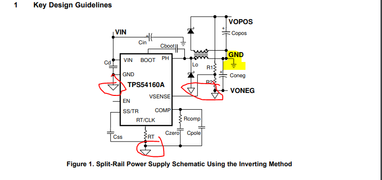
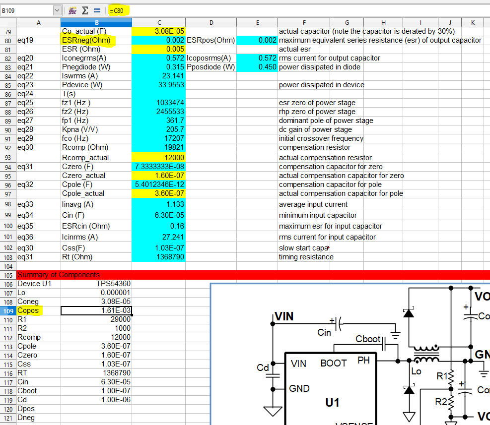
Referring to the page 34 of datasheet of the http://www.ti.com/lit/ds/symlink/tps54360b.pdf. I am looking for the calculation of inductance, capacitor and resistors value for the below output.

Vin:24V

Vout: +/- 12V

Iout: 1A for each channel

I have also tried the webench and Tina spice but couldn't get any simulation models. Can you help to advise?


  • Richard,

    There is a link in that datasheet also on page 34 to this document:
    www.ti.com/.../slva369a.pdf
    That document contains the details for designing a split rail power supply.
  • Hi John,

    Thanks for sharing the link but I've got it and it's based on the TPS54160 instead of TPS54360B. Besides that I would like to confirm whether is the highlighted ground should be connected to the same ground with the one circled in red?

    If yes then I couldn't find the simulation on Tina Spice which indicated a separate ground. Can you help to guide me on this?

  • Richard,

    The principle is the same for all the TPS54X60 and TPS54X40 devices. The GND nodes you highlight in red are the TPS54360B ground which is "VONEG", the negative output voltage (VONEG=IC ground). The "GND" highlighted in yellow is the system ground.

    You can use the calculator here which has option for TPS54360 included:
    www.ti.com/.../swiftposneg-calc
  • Hi John,

    From the calculator of the Positive and Negative Output Voltage Split Rail Calculator for SWIFT DC/DC Converters for TPS54360BDDAR that you have shared,(Kindly refer to the screenshot attached) in cell B109, the"Copos " shows the value in cell C80. But in cell B80, the value is labelled as ohm. So is it a resistor or a capacitor? 

    If it is a capacitor, as the equation involved inductance, I have reduced the inductance to 1uH but the capacitance value is still high which will takes up more space in PCB. I wonder that whether is the excel sheet has the correct calculation?

    I am looking for Vin: 24V, Vout: +/- 12 Iout: 0.7mA for each channel.

    Even when used the recommended values which stated in the application report, the reading of Copos shows 1.03E-01 in calculator.

    It's stated in the application notes shows 2x22uF. Please help to advise.

  • Richard,

    Cell B109 should point to Cell Cell B108 (or Cell C79). If you read the text in the accompanying app note, Section 1.6 calculates ESR and Value for the negative output capacitor and directs the user to use the same value for the positive output capacitor.
  • Hi John,

    Can you share the PCB layout guide lines for SLVA369A as couldn't find from ti.com.
  • Richard,

    I think the actual board documentation is here:
    www.ti.com/.../slvu374