This thread has been locked.

If you have a related question, please click the "Ask a related question" button in the top right corner. The newly created question will be automatically linked to this question.

WEBENCH® Tools/UCC28070A: Trouble in Replacing CT with current sense resistor

Part Number: UCC28070A
Other Parts Discussed in Thread: UCC28070, OPA172

Tool/software: WEBENCH® Design Tools

Dear Sir/ Madam,

I have replaced CT with current sense resistor. I am getting a poor power factor(0.89).

Vinac:230

Vout:380 dc

o/p Current:5.8A

i have attched my schematic.i am having trouble with calculation of CAOx and VAO networks.6864.SCHEMATIC1 PAGE1.pdf

  • Hi Kumar

    This looks like the same question that is in your other post. Please close that post and we will support this one with the schematic.

    Can you send plots of the AC line current and the voltage waveforms of I1 and I2 on pins 8 & ( of the UCC28070A

    Regards

    Peter
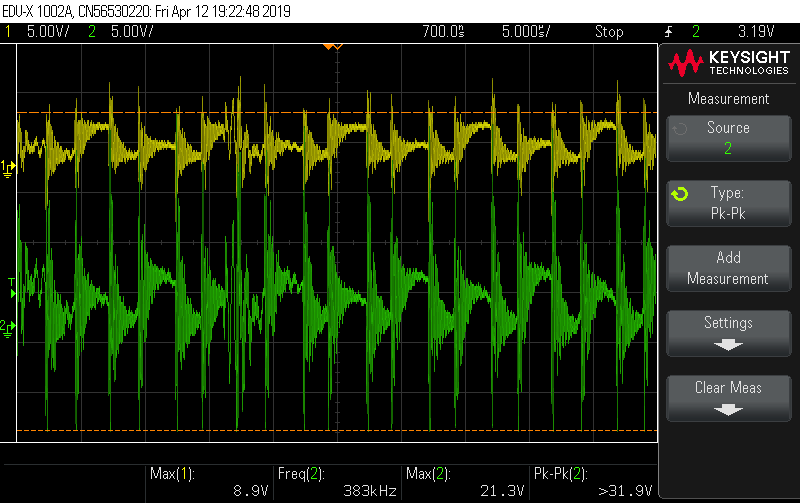
  • i dont have the current waveform. But i know it's like a sinusoidal but with zero cross at full load(2.2kW) and discontinuous on the positive side of sinusoidal at no load.i have attached the waveform at pin 8 and pin 9 at full loadf  

  • Hi Peter,
    Yes, I have used an external amplifier (INA181A1IDBVT) for the current signal and the gain is 20.This is the reply to another post i have added and i closed it now.
  • Hi Kumar,

    The waveforms have are very noisy, did you use a ground connection point close to the IC ground pin when taking these measurements?

    I do not see any filtering of the CS signals on the pins of the UCC28070? I suggest you add 1k and 220pF RC filters to both CS pins with the capacitors located next to the pins of the IC.

    Regards

    Peter
  • Hi Peter,

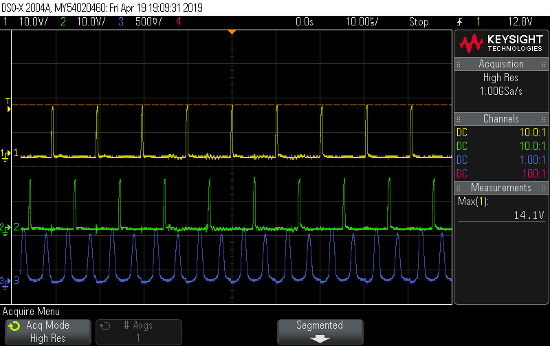
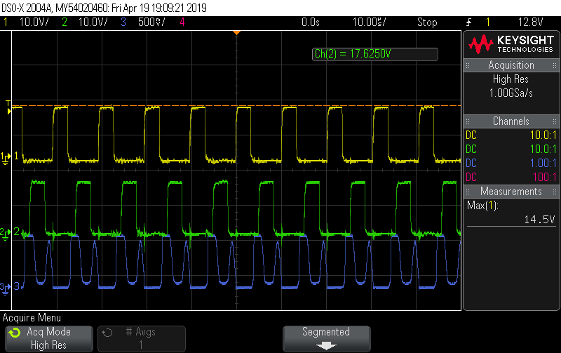
    I have added the filter now and i have observed that the duty is varying (on time gate pulse) rapidly for constant load and constant input voltage. i have attached the waveform of gate 1, gate 2  and drain voltage of mosfet 1. Please advice to rectify it, also the PF is very poor in this regard(0.89).

    Here i have attached the waveforms for which both the load and voltage are constant, but the duty (gate pulse ON time) is varying rapidly. 

    1st channel- Gate 1

    2nd channel- Fate2

    3rd channel- Drain voltage (mosfet 1)

    Thanks

    Kumar.V 

  • Hi Kumar

    What do you mean by constant input voltage, are you running the design from AC or DC voltage?

    If the design is run from AC then the duty cycle will vary as the AC line voltage varys from zero crossing, max duty cylce to peak input voltage, close to min duty cycle.

    Regards

    Peter
  • Hi peter,

    I am applying 230V ac to a bridge rectifier and converting it to 310Vdc and applying it to the interleaved circuit. Constant voltage means 310Vdc here. At lower load (100W i/p) I'm getting only 0.86PF and higher load (say 2300W i/p) 0.96 PF.

    Thanks,

    Kumar.V

  • Hi Kumar,

    The AC may go through a bridge rectifier but there is normally only minimal capacitance on the rectified side of the bridge to allow significant variation in the voltage level. What capacitance do you have following the bridge, have you looked at the voltage waveform across the bridge itself.

    Regards

    Peter
  • Hi Peter,
    I am using 22nf capacitor at the rectified side. I have observed the waveform at Vinac pin and it is varying as you said. But is there any way to improve the Power factor?
  • Hi Peter,

    I am using current sense resistor (0.012 ohm) at the source of MOSFET instead of CT. I am not using Frequency dither option, instead i grounded ram(2nd pin) and connected CDR Pin to Vref.Would that affect Power factor.Please review and help me to improve power factor, Now i am getting only 0.86 PF.

  • Hi Peter,

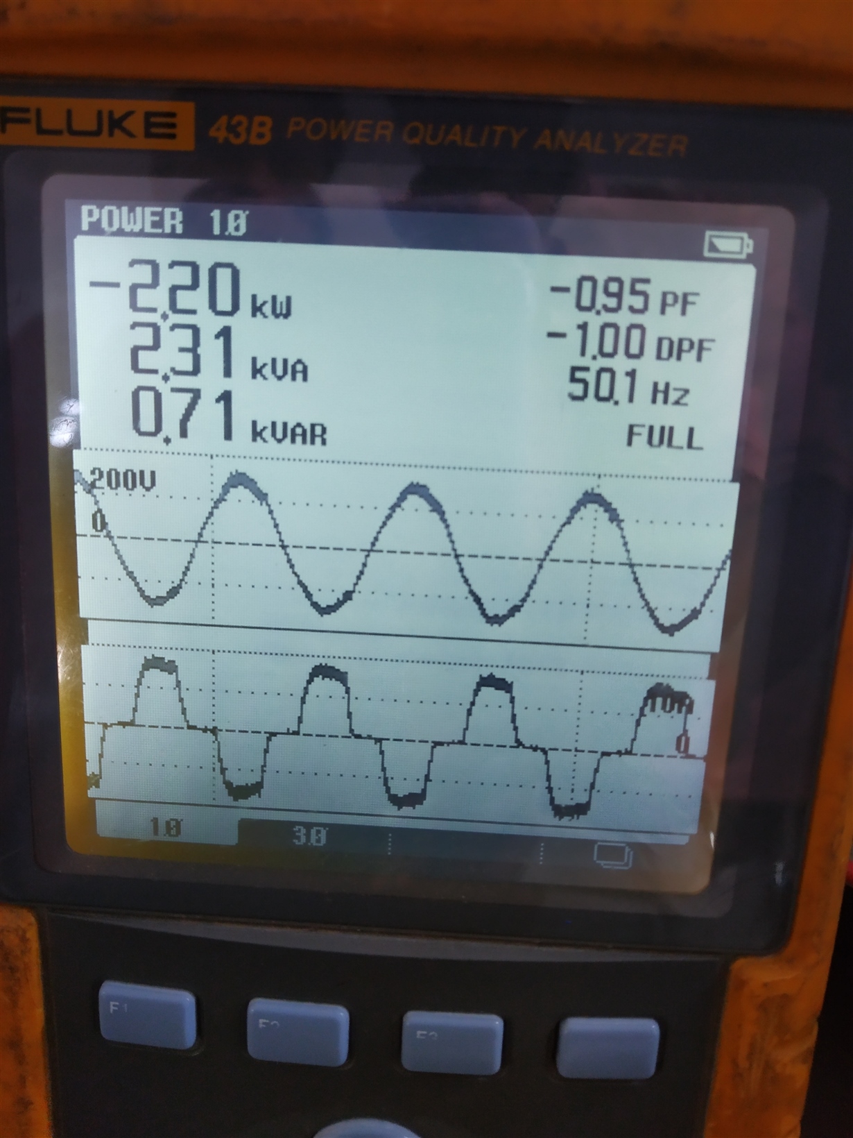
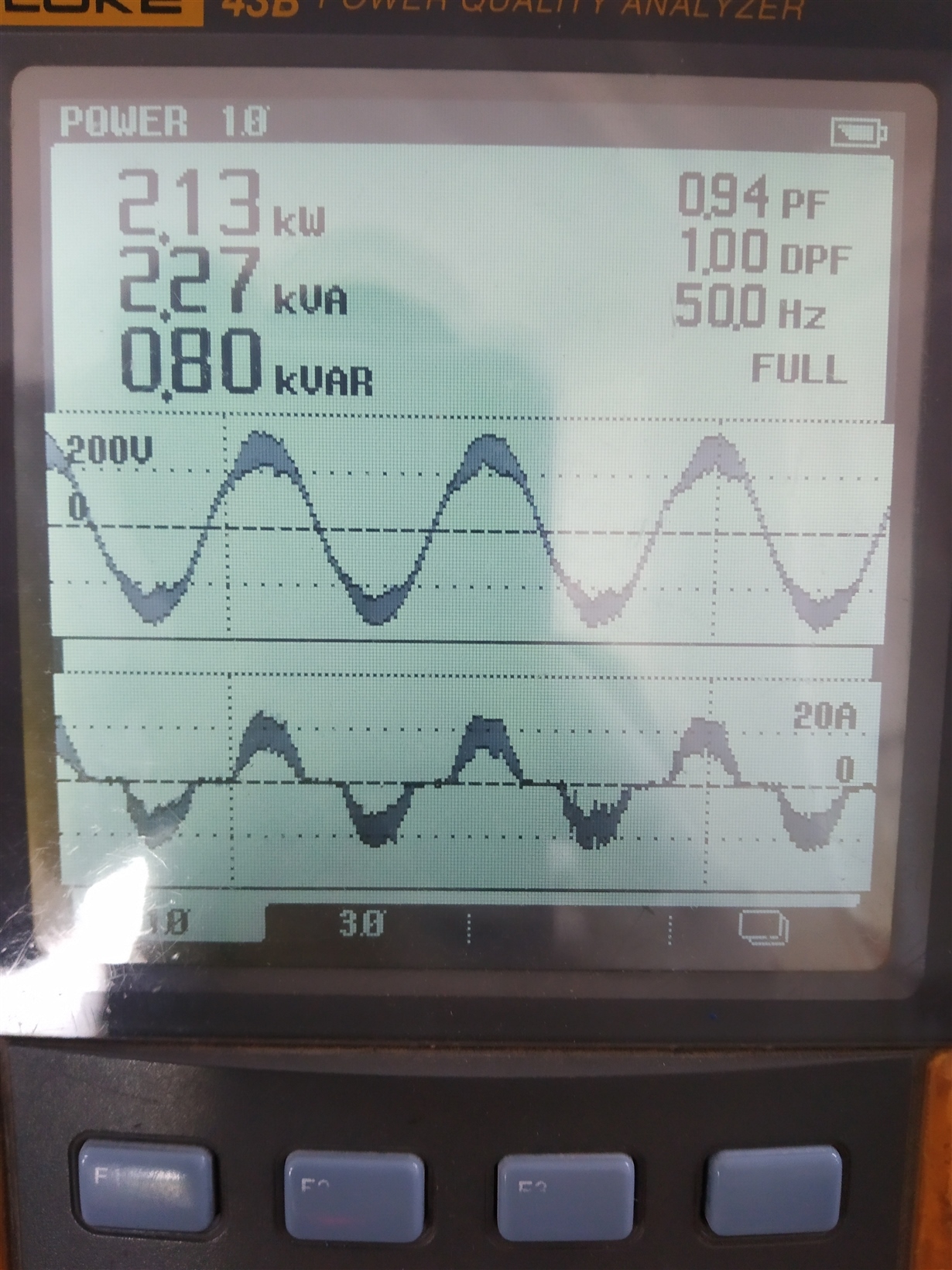
    I have attached the input current and voltage waveform. There is a zero cross in the current waveform which affects the Power Factor.

    Thanks

    Kumar.V

  •  Hi Peter,

    I have attached the input current Waveform. The input current waveform has a zero cross in its sinusoidal wave which results in poor Power Factor.

  • Hi peter,

    I have closed the other post. Review my posts and help me to solve out the issue.

    Thanks in Advance,
    Kumar.V
  • Hi Kumar,

    I would reduce the capacitor after the bridge to 2.2nF and your power factor should improve.

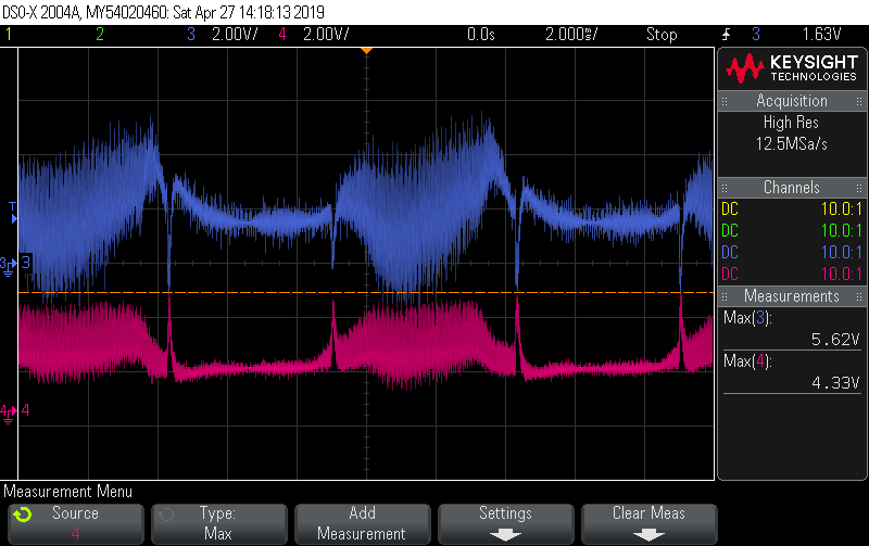
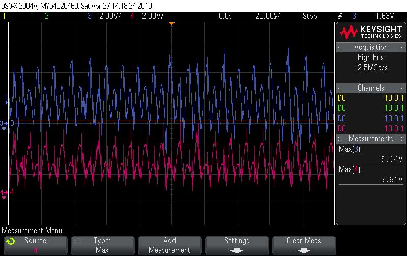
    Can you also post oscilloscope plots of the voltage on the current sense pins at 2ms/div and also at 20us/div.

    Regards

    Peter
  • Hi Peter,

    I have reduced the capacitor to 2.2nF, also i have enclosed the oscilloscope plots on current sense pins (CSA, CSB).

    But my Power Factor is still not Improving (0.94 at full load).Kindly help me in this regard.

    These are recorded in the following conditions,

    Pin: 2200W

    VOut: 376Vdc

    Thanks,

    Kumar.V

  • TI UCC28070.pdfHi Peter,

    I have attached the updated schematic for your reference. Kindly help me to solve this issue.

  • Hi Kumar,

    I am concerned that the current sense circuit may not have enough bandwidth the INA181A current sensor only has a bandwidth of 350kHz.
    This is too low for a 100kHz switching frequency.

    You should modify the circuit to use a high speed OPAMP  such as an OPA172IDR  for this application. The High Speed Op-amp will be able to accurately track the PFC switch current. We can then look at optimizing the filtering of the CS signal at the IC pins, currently we have 1k and 1nF, we may be able to reduce this once we get a good quality CS signal.

    I see only 10nF decoupling on Vref, please increase to 100nF

    It there a decoupling cap on Vcc, you should use 1uF to 10uF, ceramic.

    The Rsyn value needs to be calculated using the equation shown in this post

    Regards

    Peter


    I think the main issue is the switching current is not being accurately sensed.

  • Hi peter,

    Thanks for your valuable advice.

    I have reduced the offset of the current sense amplifier to 0.1 V Previously it was 1.65V.

    Due to this i'm getting 0.99 PF from 50% of my load.

    Still i'm getting only 0.87-0.92 PF at loads less than 50%.

    Meanwhile i have ordered the OPA172 amplifier as per your recommendation.

    Please suggest me to improve power factor at lesser loads<50%.

    Thanks,

    Kumar.V

  • Hi peter,
    In the previous reply post you have mentioned another TI community post for programming Rsynth Resistor.
    But i do not clearly understand.
    i.e, Nct= Rs * Lpri/ Vs
    Rs-sense resistor
    Lpri-boost mosfet current
    But what is Vs?- is that the Voltage sensed by the current sense resistor?
    If it is so Nct= 0.012*11.11/0.133
    0.012-my current sense resistor, My amplifier gain is 20.
    then Nct= 0.133/0.133 it becomes one.
    Please advice for programming Rsynth resistor.

    Thanks,
    Kumar.V
  • Hi Kumar,

    The Vs is sensed voltage at the CS pin of the IC which should be about 3V to stay below the peak current limit, section 7.3.9 in the datsheet.

    The formula is

    Vs = Rs*Ipri/Nct where Vs is the sensed voltage and Ipri is the boost MOSFET current.
    This gives Nct = Rs*Ipri/Vs
    Substituting this equation into equation 12 :

    Rsyn = 10*Ipri*L*k/Vs

    The Ipri value is given in the excel calculator tool.

    Regards

    Peter
  • Hi Kumar,

    I hope you have made some progress in the meantime, I am going to close this post. If you have more questions please open a new post.

    Regards

    Peter
  • Hi Peter,
    I am still not able to get good performance at less than half load.I'm getting only (0.89 PF) up to 1 kW.

    Thanks,
    Kumar.V
  • Hi Kumar,

    Can you send me the waveforms on the CS pin now that you have changed over to the Op amp to amplify the CS signal. Please use a timebase of 5 to 10us/div so we can clearly see the CS pin voltage.

    Can you also use a current probe to measure the current in the boost fet or inductor so we can compare the waveform on the CS pin with the actual current?

    Thanks

    Peter
  • Hi Kumar,

    I hope you have made some progress in the meantime, since there has been no activity on this post I am going to close it. Please open a new post if you have more questions.

    Regards

    Peter