This thread has been locked.

If you have a related question, please click the "Ask a related question" button in the top right corner. The newly created question will be automatically linked to this question.

LM5017: waveform osilation

Part Number: LM5017

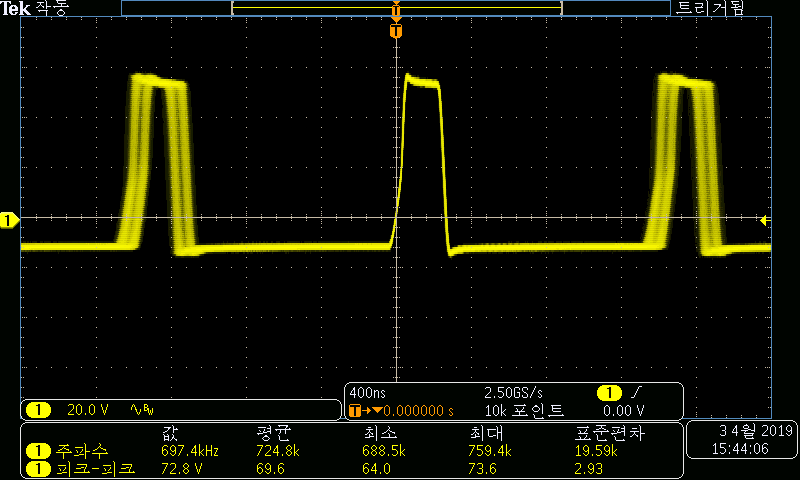
The oscillation of the switching waveform is seen during the review with the LM5017.
Even if the values of RON(PIN4) and FB loop(pin5) are changed and the input is changed, the oscillation phenomenon does not change.
It's like a jitter function, do you know how to solve it?
Is it the normal operation of the LM5017 with jitter fuction?

Application : Aux power for MCU
Input 48V~66V
Ouput : 5: 50mA
          10V: 70mA

Waveform : Input : 48v
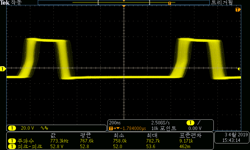
input : 66V

5444.sch.pdf

  • Hubert,

    The LM5017 is a Constant On-Time converter which does not have the same frequency accuracy as a voltage-mode or current-mode converter. Still we may be able to reduce that jitter by adjusting the schematic and maybe layout.

    Schematic - Try increasing C5 to 6.8nF or 10nF. That will inject more ripple which may help.

    Layout - Please share the layout and I'll take a look.

    Thanks,
    -Sam
  • LM5017_PCB.pdfHi Sam,

    Thanks fory prompt reply.

    I have changed the C5 according to your advice, but there is no change in waveform.

    I'd appricate  you reviewing the attached layout file.

    And the customer wants to know if ic is damaging due to this oscillating waveform.

    Thanks.

  • Hubert,

    The layout looks good to me in terms of the layout's ability to worsen the jitter.

    The only thing I might consider is it the isolated output is oscillating. This could cause the switch node to appear to jitter on the scope. But if that's not the case than this is fine. The jitter is as expected for a COT.

    I have no evidence to suggest the IC is damaged.

    -Sam