Other Parts Discussed in Thread: F28M35H52C, C2000WARE, TPS62291
Tool/software: Code Composer Studio
phenomenon:
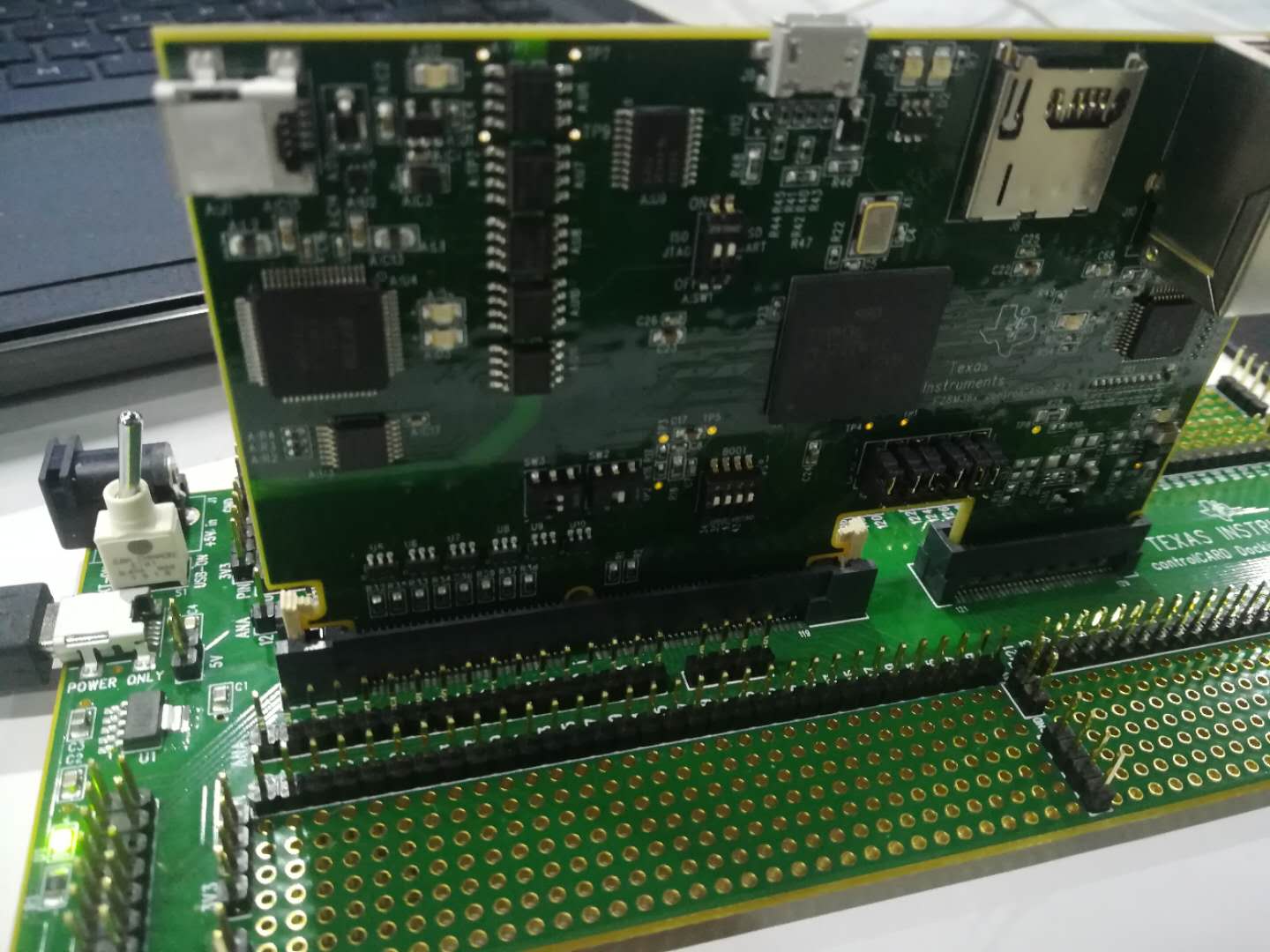
1. when i plug USB in docking station and control card's A:J1, CCS can not record my program as follow:

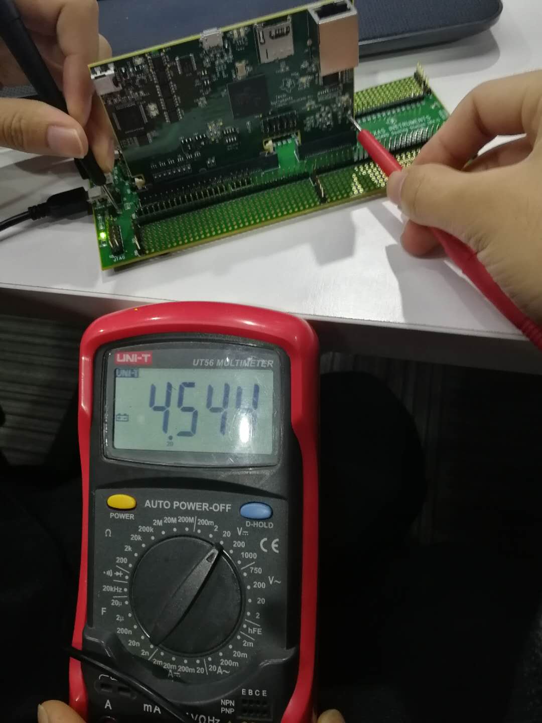
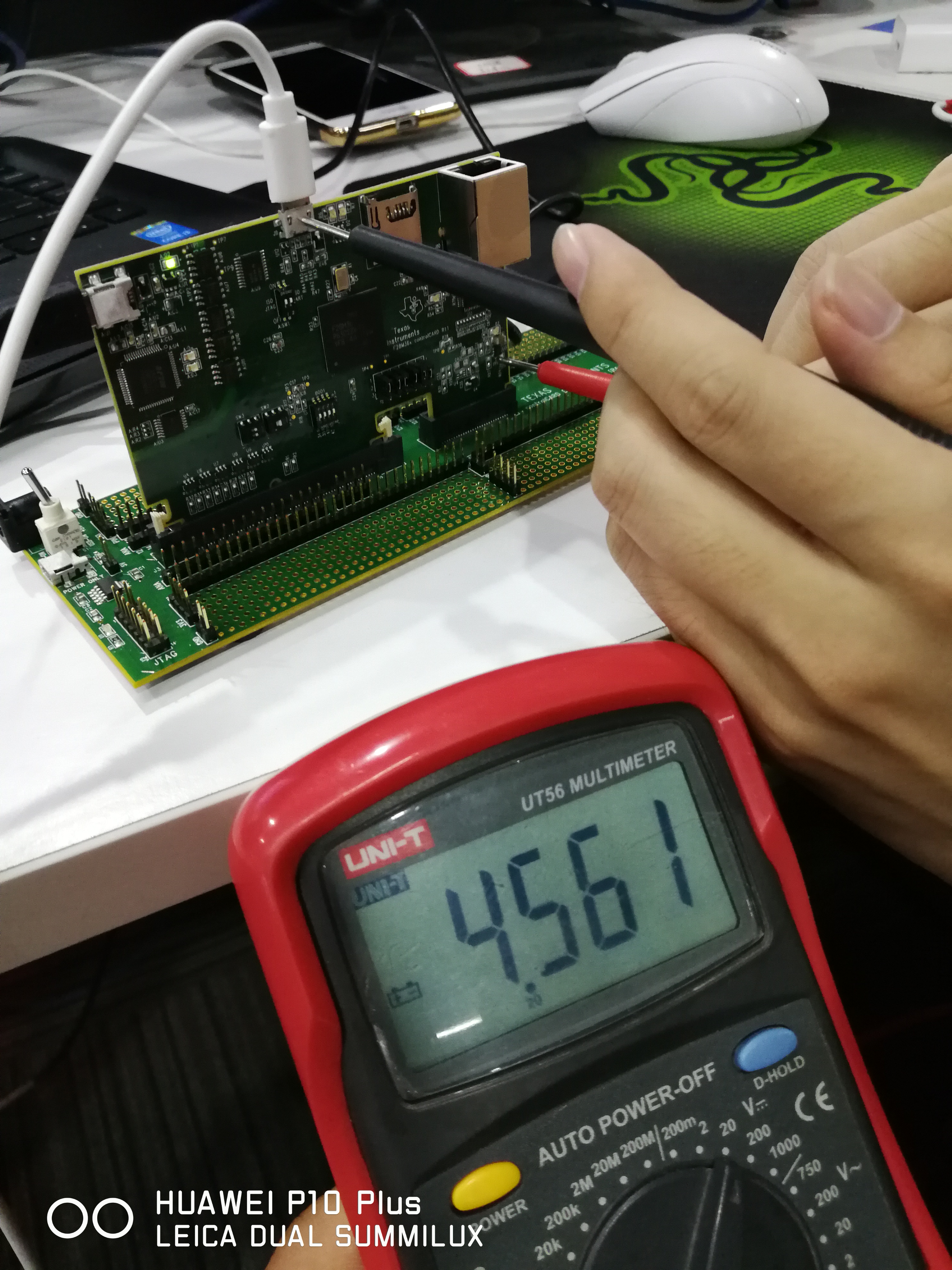
2. i detect the voltage on docking station's 3V3 and 5V, the voltage all equals to 4.7V.
3. when i power the docking station, the temperature around U1 on docking station is high.
4. i can not power the control card by the on-card micro-USB, and the LED D1 on docking station is not open:


thank you!