Hello, TI engineers !
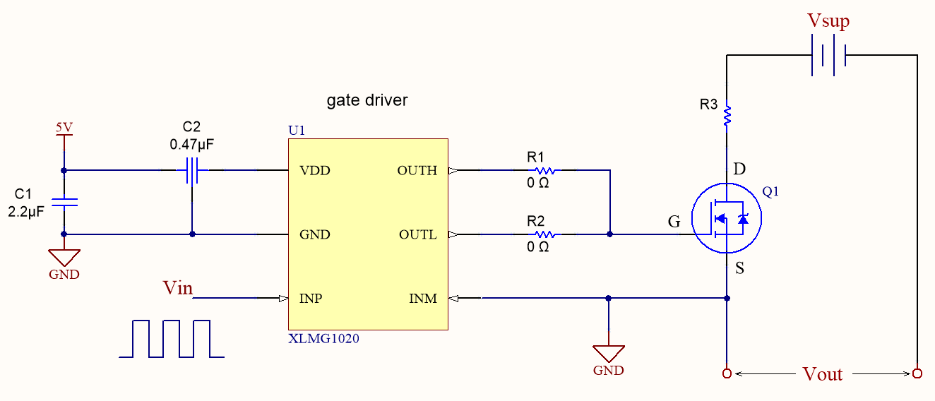
I am intending to obtain pulsed voltage with MOSFET, and the chooper circuit I designed is as followed. To ensure the MOSFET can be turned on, the Source terminal of the FET is connected to the gate driver GND. The gate-source voltage waveform is effective to drive the MOSFET, which is pulse voltage of 5V with duty 20%.
The output voltage is obtained from Source and GND of supply voltage Vsup (DC power).
When the output of gate driver is high, the MOSFET is conducting so the Source terminal voltage is equal to Vsup.
But when the output of gate driver is low, the MOSFET is working in switch-off state. Then, the voltage difference between Source terminal and GND of Vsup is not sure because there is no common between the two terminals.
When suppying pulse control signals to the Vin, the output voltage Vout is always high and equal to Vsup, rather than chopped pulse voltage as intended.
What is the problem of this circuit and what should I do to output pulse voltage?