This thread has been locked.

If you have a related question, please click the "Ask a related question" button in the top right corner. The newly created question will be automatically linked to this question.

LM3488: Coil gets exceeding hot very quickly at rated full current

Part Number: LM3488

Using a 12V 2A coupled inductor reference design, and at low output currents <400mA it runs well with no immediate side effects. Once we go over 400mA things change rapidly. At 1A it is getting very hot (cannot touch the coil) within approximately 30 seconds. If we try at 2A it is getting to a similar temperature in around 15 seconds. The output voltage appear OK, it just overheats and its mostly the coil. The Mosfet is heating up too, but the coil is most noticable.

Looking at the VSwitch waveforms at the different currents I can't help but feel they aren't right. The unit is running at the design frequency of 320KHz.

The above is with a 50mA load.

This is a 400mA Load.

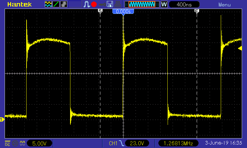
Above is a 900mA Load
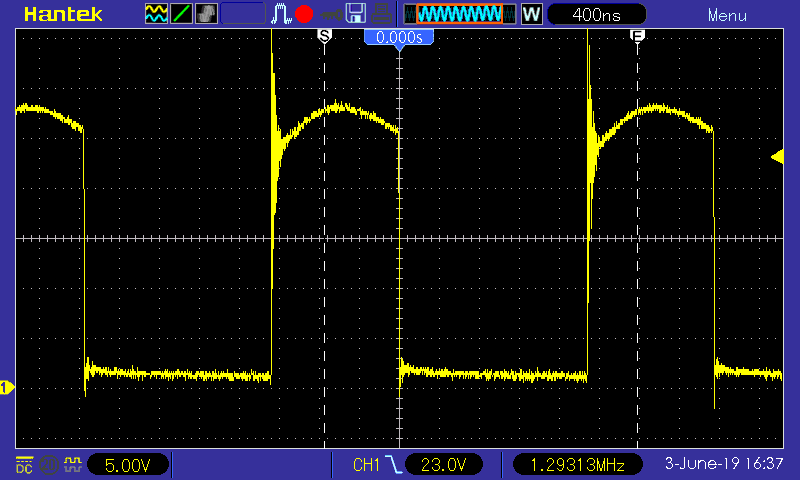
Finally a 2A load.

The loads are all resistive only, with only some lead inductance and capacitance.

Any hints? The coil tests OK for basic conductivity tests it is a Bourns catalogue product and unless the batch is faulty I have others with the same results.

Thanks in advance

Ken

  • Hi Ken,

    Thank you for using the LM3488.  It looks like a flyback design, right?  The first two waveforms look typical flyback DCM but the voltage plateau is not flat, indicating some problem in your circuit.  The last two look like CCM waveform but again the voltage plateau is not the typical flat top. Can you share your schematic?  I am also afraid your transformer selection may not be proper to support your power level.  

    Thanks,

    Youhao

  • Hi Ken,

    Thank you for using the LM3488.  It looks like a flyback design, right?  The first two waveforms look typical flyback DCM but the voltage plateau is not flat, indicating some problem in your circuit.  The last two look like CCM waveform but again the voltage plateau is not the typical flat top. Can you share your schematic?  I am also afraid your transformer selection may not be proper to support your power level.  

    Thanks,

    Youhao Xi, Applications Engineering

  • Hi YouHao,

    This is the schematic.

    Currently for testing we have Q2 bypassed.

    Thanks

    Ken

  • Hi Ken,

    You configured the circuit in a SEPIC,  but the schematic does not match your previous description.  Is you output 12V@4.5A or 2A?

    Anyway, according to your schematic, your switching frequency is set at 300kHz.  From your waveform I guess your input voltage is at about 8V.  Do a quick calculation by following the LM3488 datasheet SEPIC design procedure,  your component selections do not meet the datasheet recommendation: your inductor peak current is ~5.8A, and the secondary winding RMS current ~3.16A, both exceeding the inductor rating.  So, you should select a different coupled inductor.    In addition, the Sepic ac capacitor should be >2.5uF according to the datasheet,  but your selection is only 1uF.   

    Could you update your design per the datasheet recommendations?

    Thanks,

    Youhao 

  • Hi Youhao,

    Sorry I should have stated the test waveforms were with a 12V supply. The design requirements is to handle 7-28VDC supply.

    The output is 12V 2A, the @4.5A is my schematics editors tag to another sheet.

    The design was based on the output from the webench design tool. (I've used this tool many times with good success in other designs)

    All values and parts have been used as per the BOM from the tool. Maybe there is a hiccup in there somewhere. I'll do some manual calculations and redesign of the PCB to suit and see how we go.

    Thanks for your assistance.

    Regards

    Ken

  • Hi Ken,

    Thank you for the update. Let us close this thread here first.  If you need to reopen it, you can follow a new post, or create a new thread.

    Good luck!

    Thanks,

    Youhao