This thread has been locked.

If you have a related question, please click the "Ask a related question" button in the top right corner. The newly created question will be automatically linked to this question.

TPS40422: Incorrect shunt measurement

Part Number: TPS40422
Hello,

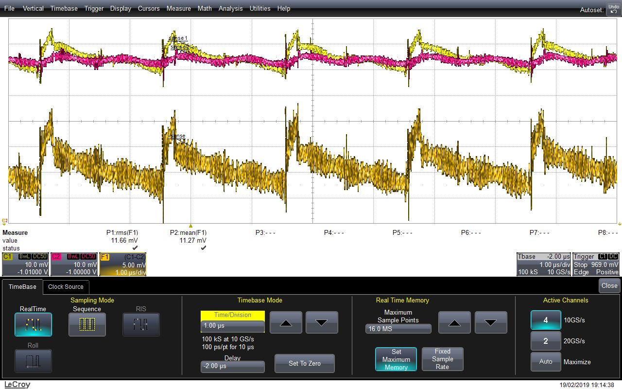
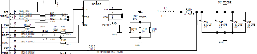
In our case we use a current measurement by shunt (resistor). We see virtually no influence on the measurement of the TPS40422 as the temperature of the board changes. While the consumption at this part increases by 40%. The TPS40422 is correctly configured. On the other hand if we put a resistive load on this part we see an influence. I feel that we can not measure the dynamic part of the signal. We use the TPS40422 in Two-Phase Synchronous Buck Controller. Attached you will find two signal readings at shunt resistor R2914.The measurement is carried out through the resistor R2914 :


Do you have an idea of ​​the cause of the problem?

  • Hi Vincent, 

    TPS40422 has internal temperature compensation for current sense, because typically it use DCR sensing circuit, not sensing resistor. 

    Sorry, I don't quite understand the problem. Do you mean the current measurement is not accurate when board temperature rises up?

    Thanks

    Qian

  • Hi Qian,

    Yes, the current is not true when the board rises up. For example the current measures by the TPS40422 at 25°C is 5000mA, and at 80°C the current is 5500mA. With my own measure, I am expecting 7000mA at 80°C (this measure is true). I have tested a resistive load (after R2914, between PU_V_CORE and GROUND) and I see the same influence on temperature range (+1000 mA at 25°C and +1000  mA at 85°C). I have the impression that the chip don't arrived to measure the entire spectrum of the signal.

    Your chip is designed to use a sense resistor, see the Figure 11. Current Sensing Using Sense Resistor in the TPS40422 datasheet =>

    There is a problem to use a sense resistor against a DCR resistor of a coil ?

  • HI Vincent, 

    TPS40422 has temperature compensation for DCR sensing, because inductor DCR increases with higher temperature. 

    However, the temperature compensation is not needed for sensing resistor, because the sensing resistor value does not changes with temperature. 

    As a result, if sensing resistor is used, the current readout will be lower than actual current at high temperature. 

    Unfortunately the temperature compensation can not be disabled. You can either change to DCR sensing or disregard the inaccurate current readout. 

    Thanks

    Qian

  • Thanks Qian,

    I think it would be interesting to explain this in the datasheet. Do you have the calculation of the current compensation (or the curve in %) ?

    Thanks.

  • Hi Vincent, 

    The current readout is calculated as: Vcs/(IOUT_CAL_GAIN*Tcompensation)

    Vcs is the voltage between CSP and CSN.

    Tcompensation=1+(T-25)*0.0039 is temperature compensation. T is the temperature readout, 0.0039 is copper temperature coefficient.

    IOUT_CAL_GAIN is set by PMBus, it should be equal to DCR value or sensing resistor value. 

    Thanks

    Qian