This thread has been locked.

If you have a related question, please click the "Ask a related question" button in the top right corner. The newly created question will be automatically linked to this question.

TPS24770: Over current protection set problem

Part Number: TPS24770

Hello Sir,

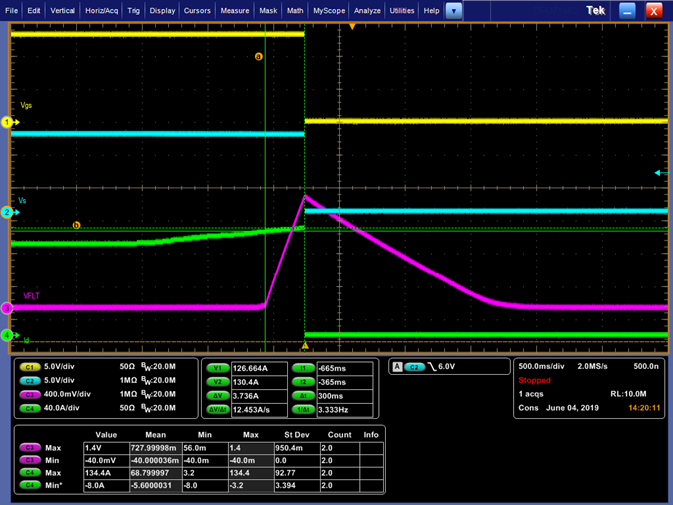
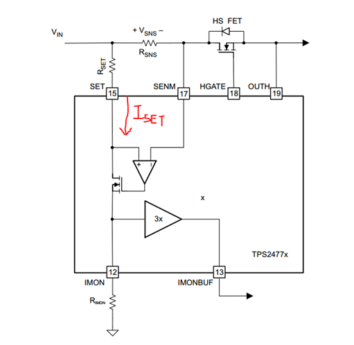
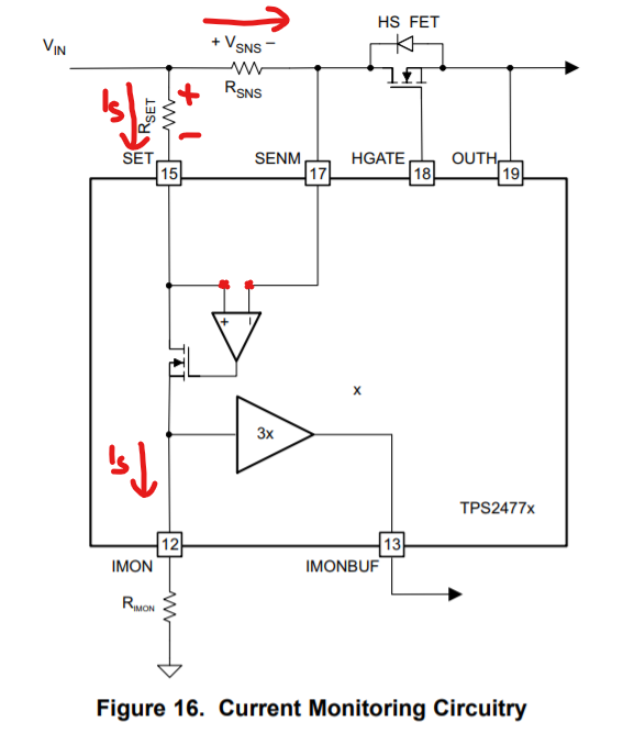
OCP is  set  to 100A, but test results is 130A, when current is 100A, test shows VRsns=25mV, VRset=20.23mV, Rimon=546mV,

Test condition is wait for output is stable, then increase the load slowly, up to 130A then MOSFET shut down

what’s the problem?

Rsns=0.25mOhm Rset=100ohm Rimon=1700ohm Rfstp=330ohm Cfst=1nF

Thank you.

  • Hi Penn,

    I assume you have used Rimon = 2700 ohms.

    How fast is the load current increased ? As per your design, the Fault timer should start ramping up as soon as the load crosses 100A.

    May be you are increasing the load current faster before the timer hits its threshold. Can you please share waveform with Load current, fault timer , Vin and Vout captured ? 

  • Hi Praveen,


    The test is as below,

    CH1:Vgs,CH2:Vs,CH3:VFLT,CH4:Id

    fault time=300mS

    Thank you very much.


  • Hi Penn,

    What you are observing is correct. the timer start as and when the load current goes beyond 100A , the timer starts and if the load current does not go below the set current limit before timer reaches 1.35V, the FET is turned OFF.

    If the current goes beyond fast trip threshold, then the FET is turned OFF immediately irrespective of Timer.

    Did you use differential probes to measure Vgs and Vs ? 

  • Hi Praveen,

    From the waveform, when timer goes up, the current is already 126.66A, not start at the timing current beyond 100A, but the OCP setting is 100A. what could be the reason?

    Vgs is using high voltage differential probe, Vs is using passive probe.

    Thanks.

    Penn

  • Hi Penn,

    For an OCP setting of 100A, the timer should start as soon as the current goes beyond 100A +/- 5%. 

    Please check if the resistance values of Rsns, Rset, Rimon on the board are correct as per schematic ?

    Also, try replacing with a new IC to see if the IC got damaged by any chance.

  • Hi Praveen,

    Thanks for your suggestion.

    I checked all the resistor on board, and did test on 3 different board, the resualts is the same.

    Rsns=0.25mohm  Rset=100ohm  Rfstp=330ohm  Rimon=2.7Kohm  Rplim=150kohm

    when current is 100A, the Rsns voltage Vsns is 25mV by test, and in normal, the volatge of Rset should be 25mV, Rimon voltage should be 675mV.

    But the test resauts is , VRset=20.23mV, VRimon=546mV. The valure of the resistor is correct, what should be the reason for Iset incorrect?

    Thank you.

    Penn

  • Hi Penn,

    The values of Rset, Rimon and Rsns should result in a current limit of 100A. 

    As you can see in the figure below, the potential difference across the inputs of the current sense amplifier should be 0V.

    That means, Vset = Vsns

    ⇒                  Iset * Rset = Iload * Rsns 

    ⇒                  Iset * 100 ohms= 100 A * 0.25 mohms         (For Iload =100A, Rset = 100 ohms, Rsns =0.25 mohms)

    ⇒                  Iset = 0.25 mA

    As you can see that Iset is the current that flows into Rimon as well,

    So, Vimon = Iset * Rimon

    ⇒   Vimon = 0.25 mA * 2.7 k ohms

    ⇒   Vimon = 0.675 V

    As you know from the device operation that the load current is limited when Vimon reaches 0.675V that means the load current is limited to 100A.


    So, if you are seeing a current limit different than 100A, that means there is something wrong in the Rset and Rsns voltages.

    If you are measuring 20.32 mV at Rset, that means the voltage at Rsns is also 20.23 mV. 

    With 100A flowing in Rsns and voltage across it being 20.23V, the effective Rsns seen by the controller is only 0.2023 mohms rather than 0.25 mohms.

    For me it looks like a problem with the sense resistor layout,

    • May be the Current Shunt routing is not Kelvin Sensed
    • You should consider using 4  PAD sensing techniques like the one's shown below

  • Hi  Praveen,

    Thanks for your detailed explanation.

    I got the Rsns part layout from customer, I send you through e-mail, please have a look.

    Thank you.