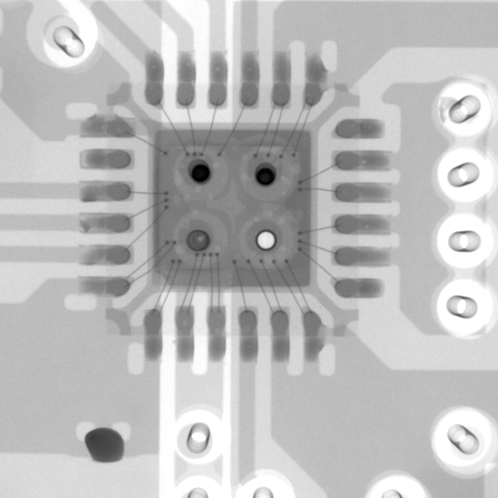
We have an issue with the +15V rail overshooting due to an instability/resetting issue. The +15V rail can overshoot by over 1V (see plots below). This has affected about 20% of our PCBAs thus far. We’ve so far replaced two of the faulty parts and this has fixed the problem, therefore the issue does not appear to be layout related. We are in the process of checking that the fault follows the part onto a board which does not show any problem. The faulty parts have also been X-rayed on the PCBs to check for soldering issues/coverage. The problem goes away if the be part is cooled on the board using freezer spray directed at the IC.
The TPS65131 package marking is ‘TPS65131 TI 9AW ZH8D’. Could someone from TI please check if this is a valid marking and if there is any errata associated with this batch?
On our working/good boards, the TPS65131 does not exhibit any instability issues, even at extreme temperatures and load conditions.
Our PCB assembler followed TI’s soldering recommendations/profiles and has adhered to MSL guidance.
TI’s layout recommendations and component specs have been followed as closely as possible.
We have opened a case with TI Customer Support relating to this issue by they are unable to help us due to lack of resources.
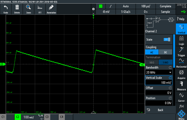
Fig1 (good board): +15V output rail ripple +/- 30mV.
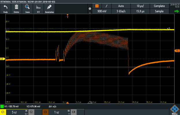
Fig 2 (bad board #1): C1 = +15V output rail (overshooting by ~1V).
Fig 3 (bad board #1): CH1 = +15V output rail; C2 = switch node; C3 = inductor current
Fig 4 (bad board #1): CH1 = +15V output rail; CH3 = inductor current - note output current being dumped back into input.
Fig 5 (bad board #2): +15V output rail with 250mV overshoot.