This thread has been locked.

If you have a related question, please click the "Ask a related question" button in the top right corner. The newly created question will be automatically linked to this question.

BQ20Z45: ba20z45 chemistry ID and associated DF subclasses 83-86

Part Number: BQ20Z45

Hello guys,

I did check the DF subclasses mentioned above and have a few questions

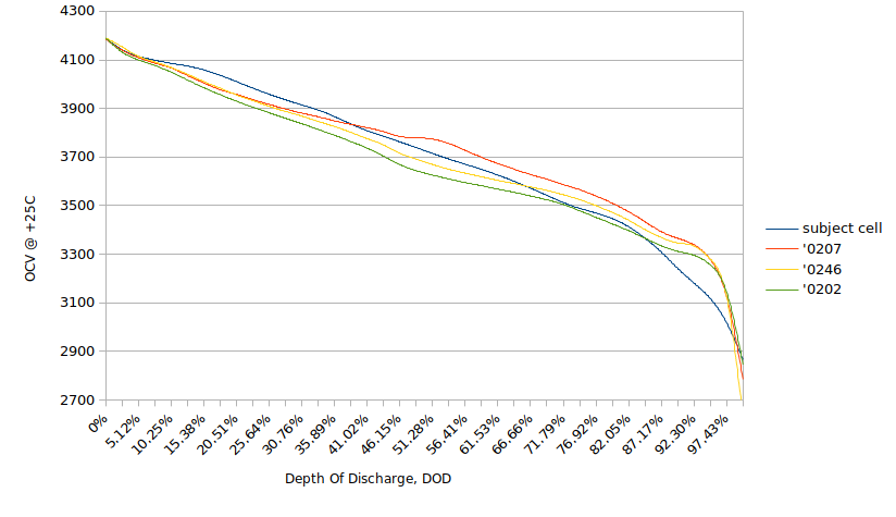
Sublcass 83. It seems it contains single cell OCV per remaining capacity dependency. It is fine, but. Why this dependency

ends at approx. 3V0? Many (well, some of) cells have a mention of 2V5 cutoff voltage. So what does happen if we have

termination voltage set to 2V5 while main chemistry table ends at 3V0?

Next, the associated tables 84 (40 points), 85-86 (15 points each), what is their intention? What data is stored there?

And, what is more important, are these tabes are used at all (f/w version 1.05)? I am checking the firmware, but cannot find any

traces of their usage. Well, investigated it not in full yet, but still.

So if possible, could you pls shed a few light on this?

Thanks!

  • Hi,

    We use the OCV table as a reference to init the gauge and calculate the DOD. What is stored in there is basically those values that are a lookup for the OCV reference which is then adjusted per your V, I, and T to calculate your RSOC. The tables in 83, 84, 85, and 86 all contain values that are important to IT gauging.

  • Hi Batt,

    Thank you for your kind answer!

    Yeah, I understand that. "To init the gauge" does this mean that it is used one time only, when we connect the cells for a first time/issued IT enable command?

    Will be there any advantage if one (me) will use 83th table with a samples from 4V2 to 2V5? There are a few documents related to how acquire this table (slua372r, sluc138dj, and some others, cannot remember right now), which also have a mention of necessity doing that at 0C, +50C too to be able produce full featured chemistry ID and its associated tables.

    As per my understanding. main table is that plain OCV at +25C, and the remaining three ones are some correction factors to it. So back to the question, will be there any advantage of using extended [4V2..2V5] 83th table? And how to correct/acquire the remaining table data? Or at least what these correction factors are?

    Also/or, given the battery is used only at +25C, can we choose any of chemistry IDs having least, say, root mean square deviation from live cell OCV? Will this approach work?

    Why. My laptop battery has gone, a few cells died (because of their protection valves), so I am going to replace them all. Ordered new cells with unclear chemistry (well they are marked as NCR, but I am unsure if it is true), and in meanwhile trying to figure out how to re-program the battery controller.

    BTW, is there more recent firmware for bq20z45, post 1.05? Could you share it pls?

    Thanks again!

  • Hi,

    That is correct. This is used to initialize on power up from shutdown.

    No, our chemistry data is private. We will not be able to share any of that with you.

    The fw you mention is the latest for the bq20z45.

  • Well, thank you anyway for your support!

    A lot of questions still unanswered, but I have found where these tables are used. So having a time until the cells arrived I will answer them on my own, and thus closing the thread.

    Thanks again, Matt!

  • Sorry, Batt, mistyped (( My apologizes!

  • No worries.

  • Hi Batt,

    Regarding the cell balancing in bq20z45. Just to confirm.

    slua340c gives typical bypass resistor value 340 Ohm, while sluu313a has mention of 500 Ohm typical (p.30)

    So what value is correct?

    And the question about the formula. What is duty factor used in it? Is it bypassing time per all the time? Anything else?

    Also, the formula outcome, DF.MinCellDeviation (which is not actually deviation, but "the bypass time", slua340c) is large enough, 1-2k s/mAh (using suggested series filter resistors of 100 Ohm). That is, to eliminate 1mAh difference between the cells we have to spent 1-2k of seconds, 16-30 minutes  . Correct? The difference is usually greater that 1mAh, and for 10mAh deltas we need 300 minutes, or 5 hours. But the battery charging process is usually faster than that.

    So how actually the cell balancing works? Is it started at very beginning of charge and silently continues after the battery reported end of charge? Or it ends when most weak cell is fully charged, leaving stronger cells not fully charged?

    Thanks!

  • Please use 340, the DS indicates typ of 400. The duty factor is bypass time ratio. It is 0.4 all the time and is internally controlled by the gauge. The balancing time is s/mAh. So it's x seconds per mAh of chg. Cell balancing is turned on in the start of chg. If you want to speed up balancing, you can use an external fet solution shown here, http://www.ti.com/lit/an/slua420a/slua420a.pdf.

  • Hi Batt!

    Great explanation, thank you! slua420a helped a lot too. But, there is a mention of bq29330 AFE in context of bq20z45 gas gauge there (slu420a, p.1). On other hand, in the product brief ()  we see, a quote: "Together with the integrated analog front-end (AFE) short-circuit and overload protection, the bq20z45 maximizes...".

    This last statement, it is not quite clear, is it about AFE being integrated into bq20z45 or about external AFE having these nice protection functions? Also, reviewing my pcb, I cannot see nor external AFE chip, neither external balancing fets. I thought the AFE is integrated, but slua420a confused me, and now I do not know if the cell balancing is implemented at all in my battery. Any thoughts?

    Maybe noob question, but I have to ask. All the documents (this and other gas gauges) distinguish two main FETs as charge and discharge ones. However, looking at the schematics, I am concluding that either charge or discharge is possible iff both fets a opened at same time (omitting particular pre-charge use case). Am I missing something? Or why they are named in this way?

    BTW,  do you know that your chemistry 0207 (at least as it seen in sluc366a, sluc157a) has an error? Well, these files looks as outdated a few/a lot, and it can be already fixed in later releases - I simply cannot access them because of "Your request was not not approved. If you feel that is a mistake then..." error (is it something wrong with me? with you? who knows).

    The very first OCV (DOD 0%) of the chemistry has incredibly hight value of 20404 mV. Also temperature correction table T84 has very low value (-32,768) at the same point. Just FYI.

    Thanks again, I am really appreciating your help!

  •  Will try to response untill TI will give more correct answers.

    1. bq20z45 has integrated AFE and built-in balancing FETs.

    2. Yes, while both Charge and Discharge FETs are switched ON, current flow allowed in both direction. As soon as gauge considers Charging(Disharging) should be stopped, appropriate FET is switched OFF, thus current flow is stopped in those direction, while is still permitted in opposite one. If gauge decides no current flow allowed, then both FETs are switched OFF. Normally during Charging or Discharging both FETs are ON to avoid overheating of built-in protection diode in the FET of opposite to current operation direction.

    3. Have rechecked Chem Id profile 0207 and nothing unusual found with OCV tables.

     Just FYI,

    OCV at DOD0 is 0x1060 = 4192mV;

    correction value at DOD0 is 0xFC94 = -876 2^-15mV/*C;

    Regards

  • Hello Igor,

    Thank you very much!

    Good to know that AFE is built-in. Actually, I would not even to ask that, just think a few to make own conclusion. I mean all these CHG/DSG, VC# pins are integral part of AFE, not the gauge itself. So if we have them already it means AFE is built-in. But anyway, thank you for the confirmation.

    Regarding FETs a roles. Your explanation makes sense. Thanks! There will be a diode on the way though, when one of them is closed, but a current still will flow. From now I don't need to track their gates' wires down to chip pins to see what is what, at least.

    Sorry for the false alarm for 0207 chemistry. It seems they fixed it already. Like as I said, I am unable to access their recent SW (some kind of permission issue), so used quite ancient sluc157a and sluc366a as a chemistries source. A dedicated thank you, Igor, for the exact values at DOD0, will correct my local version.

    I have an intention to use all these chemistry data to match my  new cells (when they will arrive) to chem.ID, then just embed T83-T86, T88-T95 of that chemistry to my 'golden image' and reflash the chip. Being a just hobbyist and EE enthusiast  I have no idea to abuse TI by sending them my cells discharge log (and actually I have not equipment to make these measurements automatically so will do it manually, i.e. results are expected to be inexact, just rough approximation, so I simply cannot do it) and asking them to match it.

    To achieve that, I built per chemistry OCV @ +25C, put them into into excel table and reserved a space to enter target cell's OCVs, 40 point at all. Then excel  calculates a distance between these vectors and after ranging them I have a few closest chemistries IDs. Then I am going to consult sluc138dj, to see these IDs' known cells and choosing the ID whose cells have matching chemistry/load capability. This second step is to get best matching cell impedance. That is it.

    How do you think, will this approach be working [good enough]? The subject battery is from laptop, used at +20C..+25C. How does Ti match cell measurements log against the chemistry? Particularly, do they match cell impedance as well? Likely an answer is in that mathcad plugin of sluc138dj, but I simply have not mathcad to dig a few dipper.

    Thanks guys!

  •  Hello again!

    Your intention to find best chemistry for unknown cells using Excel tables looks like "invention of bycicle". Too much job just for one battery, having in view that TI already did that job and realesed online Chemistry Selection Tool as well as you noticed a MathCad plugin for offline calculation. Just try one of them.

    You need to make not too complicated setup, C/6....C/8 load for battery (12V car bulb for example, precise load is not required), and SMBUS data logger, if you not have ev2300 the workaround could be even Arduino board with 2wire library. Working scetches could be found on the net.

    I am not sure whether cell's impedances are main factor for best chemistry selection. Those values will be recalculated by the gauge on qualified discharges and updated to eeprom even if initial tables are far from actual values. Ra-tables contained in chemistry profile normally characterised for single cell (1S1P). Really in laptop batteries used 1P, 2P, 3P cells connection schemes. Impedance of parallel cells decreased significantly in comparison with single cell, but initial chemistry profile Ra-tables NOT CORRECTED for number of parallel cells, when uploaded to the gauge. So until first successive learning cycle carried out, IT algorithm has potentially increased error in calculation of parameters where Ra-tables are involved. The workaround to this is Golden Image concept.

  • Hi Igor,

    Thank you for your kind replies here in this post. You are absolutely correct in all your statements.

  • Hi Igor,

    Thank you for the hint! I mean Ra tables. So, it they are for 1P, then having 2P configuration one should simply half the values there, right? It can be inexact, but still better than 1P, providing lesser error, faster IT algo learning

    As for ev2x00 hardware, of course I have not it. Too expensive for a one time job. Just using old-school VGA i2c 3wires adapter, and linux i2c utils (like i2cget and such).

    As for "precise load is not required". It seems your advice of C/6..C/8 is in contradiction with slua372r, which recommends discharging at C/20 rate (p.3). If I understand correct, after 20 iterations (at C/20) we earn whole 1C from the cell, and it gives us 20 DOD points. A question where we take remaining 20 points (as T83-T84 have 40 nodes) is still open, though (should we use C/40 instead or just consider it as PWL function? this latter case not seem to be correct - otherwise why TI uses 40 point and not 20 of them?).

    Using your C/6..C8 approach we get only 6 to 8 points, so still unclear from where we  take remaining...

    Thanks!

  • Igor,

    Thank for sharing your thoughts, now I know how to automate the process of OCV taking. Initially I thought to test a cell separately from the battery. This approach yields the issue of the load connect/disconnect at certain time, manual voltage measurement, too huge efforts for lazy guy as me ))

    However nothing  prevents us from detaching a load from battery using FET management command, right? And there is a command to read the cell voltage too. Any cell. so having 1P cell stack for a test time we can can manage a load, can take precise voltages from cells. Just a matter of not too complicated shell scripting! Thanks, Igor. Your ideas bright like a diamond!

    @Batt

    Could you please confirm the Operation CfgB bit RESCAP meaning? As per sluu313a (bq20z40 and bq20z45 tech ref manual), p.136, 0 is for "Light load compensation", and 1 is for "Avg load compensation defined via Load Select". But actually, I see that when bit value is 1 (one) then firmware just uses those values from subclass 80 (GasGauging IT, p.148) "reserve cap-mah", "reserve cap-mwh", and performs an averaging otherwise.

    This seems to be opposite to what ref manual  states.

    Thank you!

  • Hi,

    RESCAP when set allows for load compensation to take place, when reset, it's under OCV conditions, so what you get in effect is a straight reduction in capacity. However, when it uses load select, you will end up decreasing the loaded capacity by the set amount based on the load selected for the present cycle.

  • Hi Batt,

    thank you! Sorry for the late answering, was a bit busy these days.

    Well, that you said is just another wording of what I read in the datasheet. But actually I see in the code that it behaves in opposite way: when set we have straight cap decrease by amount from reserved cap DF item, and when clear it uses much more complicated schema involving minimum remaining capacity (which in turn comes from OCV and IT algo). And this contradiction is why I asked you.

    But its okay, let leave it not fully clear right now.

    Finally I got the cells, calibrated all that I could, and stopped at board offset calibration. Particularly, I am using slua379e, pp.6-7. So at preamble I see "the function requires the sense resistor value in mOhm as an argument", but later on in the code there is a formula of calculation of iBoardOffset: iBoardOffset = ... * nSenseResuOhm / 9419.

    As I can see from the variable name it is uOhm (i.e. micros, not a millis). So please, what is expected rSense value units?

    Thanks!

  • Sense value units is in mOhm. The units represented in the code are derived units. The text before the code is right.

  • Hi Batt,

    Sorry, maybe I am missing something, but...

    the description tells us about the function argument, right? And states that it should use mOhms units. ok, fine

    Then you told that derived value of uOhms is used in formula.

    There is a function prototype:

    Function CalibrateBoardOffset (nSenseResuOhm As Integer) As Long

    If we pass derived value yet as a function argument then preamble about mOhms should not be a true? If we pass mOhms value, then there is missing the derivation (x1000 multiplication) step in the code?

    Sorry for asking again, but your answer confused me.

    Thanks

  • No, the variable is misnamed. Please use straight value in mOhm without multiplying it.

  • Hi Batt,

    Thank you!

    BTW, is chemistry online identification tool  freely available (I mean should not one be a gold TI member, a partner, and such)? At what URL? Is there an expected input format description/sample and required granularity somewhere?

    Thanks!

  • Hi,

    The tool is freely available at GPCCHEM. The page contains instructions for getting your chem ID.

  • Hi Batt,

    finally I posted the measurements log and got an answer:

    -----

    Best chemical ID : 2141	Best chemical ID max. deviation, % : 1.92	


    Summary of all IDs with max. DOD deviation below 3%		
    		
    Chem ID	max DOD error, %	Max R deviation, ratio
    2141	1.92	0.4
    2144	2.17	0.39
    2145	2.3	0.79
    2112	2.53	0.6
    2125	2.57	0.62
    2481	2.74	0.8
    2161	2.88	0.74
    2133	2.93	0.75
    
    -----

    Not sure though, is 1.92% deviation figure is good or bad in general, but it seems to be quite fine for intended usage.

    However there is another issue yet. I just have not this chemistry ID related tables. So cannot even compare OCV values with those that I got (to be precise, I am getting them right now). I presume they could be included into bqstudio software, but I cannot download it: "We are sorry but your transaction has been denied"

    Any advise, please?

    Thanks!

  • Hi,

    Those are good values. A less than 5% DOD deviation is good. Please use the ID with min deviation.

  • Hi Batt,

    Thank you, good to know!

    As for "use that with min deviation", well, I simply cannot. I have no corresponding chemistry

    tables, even have no idea what this chem-id is actually referring to. Maybe there is some place on the TI's

    website where chemistry table could be d/loaded by their ID?

    Also, the report contains second part, related to ROM based devices like the bq274xx. And it is what confusing me.

    Particularly, an errors there are very high, ~20% and up, and secondly, the cells mentioned there seems to be a kind of

    4V35+ cells, while those that I purchased, are 2v75 to 4v2 cells.

    Likely I have to  redo the discharge cycle? or such a big errors of 20%+ are normal?

    ---

    Selection of best generic ID for ROM based devices like bq274xx         
                    
                    
    Device / Family #1              
    Generic Chem ID Device/ Voltage/ Chemistry      max DOD error, %
    3142    bq27421-G1D: 4.4V LiCoO2        18.88
    354     bq27411-G1C: 4.35V LiCoO2       21.92
    128     bq27421-G1A: 4.2V LiCoO2        26.27
    312     bq27421-G1B: 4.3V LiCoO2        32.79
    Best generic ID 3142            
    Warning: Generic ID Deviation is so high that it is most likely due to anomaly in the data.
    Please check that data files have recomended format, units and test schedule ---

    Thanks!

    PS. Main question still remains though. Having chemistry ID where one can take

    that chemistry tables?

  • Hi,

    Please disregard the ROM based gauge suggestions from the tool. We don't have a way where we can provide you with updated chemistry tables since this is an old gauge. Are none of the IDs available in bqevsw?

  • Hi Batt,

    " this is an old gauge" is it about ROM based devices? Or bq20z45 related?

    bqevsw that I have is coming from sluc366a (bqEVSWSetup00.09.90_bq34z100v0.07R1b.exe) and has

    only chemistries 0100-1212. Another chemistry source was sluc157a, and it is equipped with chemistries in

    range 0100-0600.

    Any attempts to download another s/w from your website end with "We are sorry but your transaction has been denied.

    If you feel you have been denied incorrectly, blah-blah-blah..."

    That is it :(

    Best Regards!

  • Hi,

    It's regarding the bq20z45. The tools supplied for the gauge do not support the new chem IDs that are there in bqstudio. Please send me your version that you are using for the fw. I will try to see if I can find a way to get the IDs loaded in that for you if you wish to try that.

  • Hi Batt,

    thank you very much! My chip has f/w v1.05. As for a tools, I do not use them anyway, even have no windows TBH.

    So I would be thankful for just raw a file with the tables T83 (OCV at +0C), T84 (OCV corrections for +50C),

    T85 (Ra corrections for >+25C), T86 (Ra corrections for < +25C), and, optionally T88-T95 (If I understand correct

    It will be recalculated anyway after a few cycles, so can use anything more or less suitable as an initial approaching).

    Raw, I mean, just as it is supplied with the some of the software, no additional processing is required.

    Thanks.

    PS.We got, BTW, an answer to "Why to re-invent wheel, by using an excel table and not just TI

    online chemistry matching tool". Do you remember, Igor was asking about this? So an answer is: just because

    the results received from the online matching tool are useless in general, at least without TI's employer kind help

    in getting these table data by ID. Excel approach could potentially help to avoid that by finding the closest chemistry

    from that we have already. Well it could be not such precise matching as achieved with using modern chemistries,

    but it should be sufficient for casual use (presumably). We [EE enthusiasts] are not going to launch space rocket,

    right? )) Just re-animate the battery for our lovely device. But maybe one day you will have something like to

    "Download chemistry data tables by ID" on your website, or even a few a links to download right in the chemistry

    matching report that you send, who knows.

    OCV per DOD taking process is almost completed (maybe 1-2 days remaining, now at 3V6), BTW, It would be curious

    to see if/how good this way does work.

  • Hi,

    I would like to get you the table for OCV but unfortunately that is TI protected data. It's because of that my hands are tied. I can get you the Ra tables though. That is open. Please let me know if that's OK.

  • Hello Batt,

    yeah, I understand, np. Ra tables anyway is better than nothing, also I will have my own OCV/DOD dependency soon (taken

    as per slua372r, 3.2 paragraph), it is almost finished. Of course, it is only for 25C, but I will select something from what I have, having

    very similar OCV at 25C. I am not intended to use it neither at zero, nor at +50C, so it would be sufficient. And it is linear (T83-T84),

    while Ra tables are not, so Ra tables are very welcome!

    Thank you again, Batt, for all your assistance!

  • You are welcome, here are the Ra tables

    Cell0 R_a flag = FF55
    Cell0 R_a 0 = 76
    Cell0 R_a 1 = 63
    Cell0 R_a 2 = 81
    Cell0 R_a 3 = 109
    Cell0 R_a 4 = 60
    Cell0 R_a 5 = 73
    Cell0 R_a 6 = 66
    Cell0 R_a 7 = 98
    Cell0 R_a 8 = 102
    Cell0 R_a 9 = 131
    Cell0 R_a 10 = 140
    Cell0 R_a 11 = 164
    Cell0 R_a 12 = 248
    Cell0 R_a 13 = 522
    Cell0 R_a 14 = 751

  • This is ID 2141

  • Hi Batt,

    Thank you very much! I am sorry, I confused Ra tables (T88-T95, right?) with Ra corrections (T85-T86), and thus asked you to make

    not necessary job. My apologizes!

    In meanwhile OCV taking was completed, and I got a few best matching chemistries using excel way. As the measurements did not fit to

    to DOD intervals of 2.56% (100/39) perfectly, an exact values were calculated by considering the measurements as piece wise linear

    function and taking corresponding values using containing interval slope and offset.

    Attached the result. Could you please comment it?

    Particularly, is this reported chemistry ID 2141 close enough to that I got (IDs 0207, 0246, 0202, 0232, 0281, 0285 - best matching first).

    Thanks!

  • ocv per dod as csv, for easier handling, if anyocv-per-dod.csv

  • Hi Batt,

    any ID=2141 representative please, if possible? Or at least something more or less descriptive,

    like as in chemistry_selection_table.xls from sluc138dj (e.g. for 0207 we have there

    "NiCoMn/carbon","0207","A01:ALPBA002 (3430mAh)")?

    Thanks!

  • Hi,

    The battery is a Sony 18650VTC6 with a 3000mAh capacity. It's chemistry is NiCoMn/Carbon. The default Ra tables for it are what I gave you before.

  • Hi Batt,

    Thank you very much!

    Well, I still have another question. Trying to calibrate the current using non default 2A, but lesser values instead (like 0.5A, 0.7A) I am entirely

    failed. The gauge simply stops working (well, it works but reported currents become something crazy after that). Nothing helps to recover,

    except full DF re-flashing. Is there somewhat sacral/magic in 2A load current? Or what could be else reason why lesser loads do not work?

    Thanks!

  • Hi,

    You're welcome. There is nothing magical about 2A. We prefer a minimum of 1A for calibration as it uses all the bits in the ADC for conversion. Lesser currents are not preferred as the delta may be too small to notice. Also, perform 4 wire sense calibration whenever possible.

  • Hi Batt,

    Thank you very much for the information! Filling all the ADC bits makes a sense, I will try with 2A then. Not sure though what "4 wire sense calibration"

     does mean. Did not see (or missed) it reading all these endless SL**.pdf )) Any hint would be very welcome :)

    In meanwhile the pack is assembled, no electronics attached yet. Used basic DFI, embedded specific parameters, chemistry 0207,

    plus your provided Ra tables (halved a values as it is 2P configuration). Regarding the IT  enabling. I did not see anything specific for

    bq20z45, so was reading slua777 (bq28x610/bq78z100), and per my vision the procedure should be (I am not going to make golden

    file, just to init IT properly for this single a pack):

    1. Discharge the pack (IT is disabled yet, R_DIS is set), leave it to rest until VOK, and 1uV/s criteria is satisfied, five hours or so;

    2. Enable IT, charge it to full (until FC set), leave to rest for a couple of hours, until 1uV/s criteria is satisfied, and VOK & R_DIS both clear (first Qmax update

    should occur here);

    3. Discharge to empty (C/5), Ra tables are updating during this step, then relax as in step 1 (second Qmax update occurs here). Ok to use the pack.

    Thanks!

  • Hi,

    Yes, that is correct. However, please repeat the cycle twice so that the values are optimized.

  • Hi Batt,

    Thanks for the hint. Actually, Ra tables were updated only during second discharge. First discharge did not affect them. Only Qmax values were updated. There is what I finally get for Ra:

    For me it looks as shifted to right, comparing with your provided Ra (blue line, halved due to 2P). So I am wondering if my cells are 4V2 and not 4V35 (were sold as 4V2)...

    Well, yet another issue. Design capacity was set to 6600. After cells connection full charge cap. was reported back as 6269. Then during two cycles Qmax were updated to:

    6831,6773,6797, and entire pack Qmax is 6773. That is as expected, perfectly matches  discharge curve. BUT the pack still reports lower full charge capacity of 6268. Is it expected? Or I did miss something? Also update status (clz 82+12) is not 0E as per datasheets, but 0D instead.

    Any hints would be very welcome.

    Thanks!

  • Hi,

    The pack capacity is reported to be the Qmax of the cell with the least capacity. FCC depends on load rate, so when unloaded or dsg at C/100 your FCC would nearly be Qmax, but if you use a C/2 rate of dsg, depending on chemistry, temperature and other factors like cell heating, your capacity can vary and be a bit less or a lot less than your Qmax.

  • Hi Batt,

    yes, I understand that capacity depends on the load. But actually I was able to take 6506 mAh (at 0.2C rate) off the pack, while it reports 200 mAh lesser. But it is okay for me, even if a bit odd.

    Will fix design capacity :D

    BTW, I was unable to calibrate current. Tried 1500 mA (the max that I am able to measure precisely), also 2A. Nothing worked for me. The chip reports fault. Cannot remember exactly, what is an error, but it prevents to get FETs open, and is impossible to clear with a dedicated fault password, can recover only by re-flashing entire DF. Reported current differs by just a few mA, but still.

    The sequence to calibrate current:

    a. 0x40 -> [0] /* enter calibration mode */

    b. 3 -> [0x63] /* number of cells */

    c. actual current -> [0x60] /* tried positive, negative values */

    d. 0xC040 -> [0x51] /* command word: calibration start */

    e. waiting until [0x52] & 0x0040 == 0

    f. cmd 0x72 /* save to DF */

    g. cmd 0x73 /* leave calibration */

    The sequence works just fine for any other calibrations (using their appropriate command word), but not for current. I was wondering if DF clz 105+0 (calibration current) is affecting the calibration process, so tried corresponding values there as well. And because it is positive, tried also positive current values at step (c).

    Did I miss something, trying to calibrate current? Particularly need we also set a stack voltage? I did not do it, as stack voltage calibration was done before, and [presumably] the firmware could acquire voltage value on its own after that. Maybe anything else?

    Thanks!

  • Hi,

    There's nothing wrong with your current measurement. It might be an artifact of layout probably, the SRP and SRN pins are very sensitive to voltage deltas. So, if there's a spurious gain somewhere you can get wrong values. But given your capacity reading is acceptable, the gauge probably offsets error with OCV.

  • Hi Batt,

    good to know that, thanks. Layout is out of my control, inherited from the battery pack as is, but if I will not be too lazy then I will look with an oscilloscope, what is going on on these ASRP,ASRN pins during the procedure.

    But I suppose, there is one more way to set up current calibration properly. Correct me if I am wrong.

    I mean SMB command 0x71 Sense Resistor. As per my understanding, it is a kind of synthetic item (ie. it is not stored in DF directly) and computed on the fly based on the calibration constants, right? So, setting it to proper value one can achieve the same right calibration constants. The only thing, I am not sure what should be a formula to calculate it. Could you please share it, if possible/known.

    Thanks!

  • Hi,

    No. Only the calibration offsets are computed. Not the gain in that manner.

  • Hello to all!

    How much discrepancy you are observing with current measurements?

    Me believe calibration procedure could be bypassed and manually calculated corrected current gain could be put down directly to DF using appropriate SubClass commands.

    In this case you should consider that CC Gain and CC Delta stored in DF in Xemics Floating Point format, it's different than IEEE 754 standard.

    If you have difficulties with calculation, just post your SubClass 104 (Calibration data), it should have 21 bytes in size.

    Basing on your measurement error ratio me will revert with corrected subclass which you will then update to device.

    Hope you know how read and write subclasses:)

    Regards!

  • Hi Igor,

    thank you for the idea! Your ideas, as always, I like them!

    Well, right now I cannot measure the difference, the pack is under final assembly and the case sealing. But I will check it during the weekend.

    Good to know that this FP format has dedicated name. When investigating firmware I recovered its structure, was wondering why it is not ieee754.

    There is my current DF clz 104, just in case:

    # DF subclass 104: calibration-data, length 0x15, at 0x040
    # -----------------------+-----------------------
    # 81 6b 46 f8 94 05 d8 bb 5f 02 05 08 56 22 fa 15
    # ff 05 4f 07 ed
    # -----------------------------------------------

    But if possible, can you share the calculation details? How do we calculate CC-gain/-delta having actual/indicated current's a values?
    I can remember that I seen something mentioned in one of all these endless slu**.pdfs, but cannot find it right now. Something like this: dM = Ia/Ii,
    then multiplying CC gain/delta by this and flashing them back, but I am unsure right now what should be divider and what is a dividend.

    Thanks!
  • Also I suppose, to get the delta and gain (offset and slope, in other words, right?) we need at least two measurement points? Just from school math, linear functions...