This thread has been locked.

If you have a related question, please click the "Ask a related question" button in the top right corner. The newly created question will be automatically linked to this question.

BQ24725A: BQ24725A current setting doesn't match the actual chraging current

Part Number: BQ24725A
Other Parts Discussed in Thread: EV2400, BQ40Z50-R1

Dear Sir,

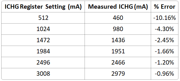
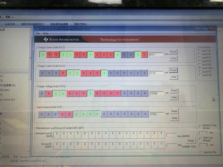
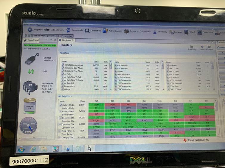
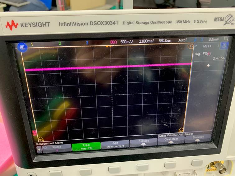
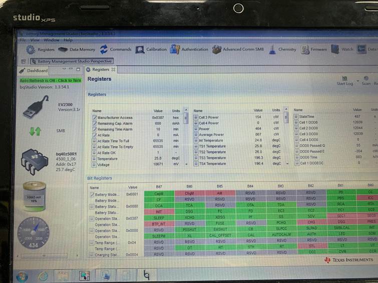
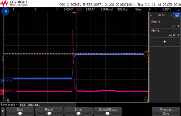
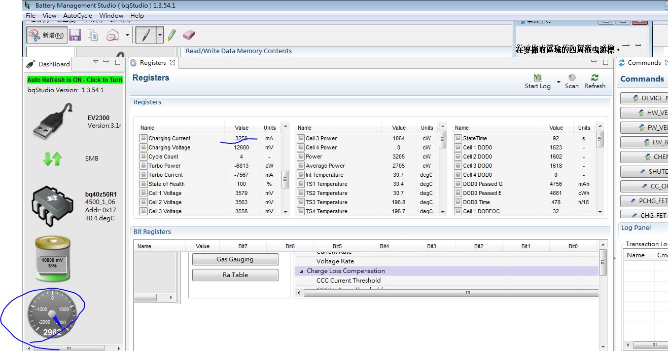
Our customer have dsign in BQ24725A and current they are setting the chagring current to 3250mA show as below. However, when RD measure the actually charging current , they only measure the max current 2.6A . Coudl you kinldy hlep us check why there is difference between the set currnet and actual current? . Also, the battery pack they are currenty use is using TI guage BQ40Z50R1 and we attach BQ24725A schematic as well.

BQ24725A .pdf

Abvoe, please kinldy help us and if thre is any quesiton, please feel free to let me know

Alec

  • Hi Alec,

    Is the measured charge current 2.6 A or 2.962 A, as shown in the GUI?

    Also, is the charge current accurate for other charge current settings? If possible, please send me the measured charge current when the charge current is set to each of the following values: 0.5 A, 1 A, 1.5 A, 2 A, 2.5 A, and 3 A.

    Best regards,

    Angelo

  • Dear Angelo,

    We have double check with RD. The charge current will be a little different every time they test it  and the charging current is always between 2.6 to 2.9A but it wont reach to 3205mA set changing current.  We have ask RD to run some other current setting as your suggestion and we are waiting for the feedback. At the meantime, Could you have any idea why might cause this? and if there is any other setting that we can try? please let me know

    Cheers

    Alec

  • Hi Alec,

    There are a few conditions which could cause ICHG to be reduced. For example, if the adapter is overloaded and cannot power the system and charge the battery at the same time, then the BQ24725A will enter DPM. The charge current will be reduced in order to prioritize the system and keep the adapter from crashing.

    For reference, here is some ICHG accuracy data that I measured on an EVM. The measured ICHG is well within the regulation accuracy range given in the datasheet. Higher ICHG register settings should be more accurate, which is why I'm interested to see your data at lower ICHG settings. If lower ICHG settings are accurate but 3250 mA is not, then a feature such as DPM could be kicking in and reducing your charge current.

    In addition to collecting the ICHG accuracy data at the current settings that I mentioned, here are some other things you can check:

    1) Are you testing this with a system load connected, or is it only the adapter, the charger, and the battery?

    2) Your adapter voltage is 19 V, according to your schematic. What is the adapter's current capability?

    3) What is your input current register setting?

    4) What is your battery voltage when you try to test this, and what is your charge voltage register setting?

    5) What is the measured voltage on the ILIM pin?

    Best regards,

    Angelo

  • Dear Angelo,

    Here are info for your the question that you asked.

    1) Are you testing this with a system load connected, or is it only the adapter, the charger, and the battery?

    ==> They test battery with system load on. However, the system standby mode. the system load should be less than 10W.

    2) Your adapter voltage is 19 V, according to your schematic. What is the adapter's current capability?

    ==>The Adapter is 90W which should be more that enough for the testing condition

    3) What is your input current register setting?

    ==>The input current setting is 5A

    4) What is your battery voltage when you try to test this, and what is your charge voltage register setting?

    ==>The battery voltage is typical 10.8V(3P) and chareging voltage register is set to 12.6V

    5) What is the measured voltage on the ILIM pin?

    ==>We currenlty set the voltage of ILIM to 0.79V with didvide resistance, and with Rsr 0.01 ohm , and ICHG 3.2A max, the VLIM should be aroound 0.64V which the current setting should match the desgin.

    We still waiting for the the other Load testing result( they need the S/W RD's help to testing it.) and we will update to you when we have it

    at the meatime, if you have any other solutions that you can think of, please let us know, thanks in advacne

    Cheers

    Alec

  • Hi Alec,

    Thanks for providing that info. Let me know when you have the data for the measured charge current at various charge current register settings (0.5 A, 1 A, 1.5 A, 2 A, 2.5 A, and 3 A).

    Best regards,

    Angelo

  • Hi Alec,

    Have you been able to collect this data yet?

    Best regards,

    Angelo

  • Dear Angelo,

    Sorry for the late reply. We have run some test with RD and  collect some data for your reference. 

    First , original setting, charging current 3.2A :

    As you can see the setting and measure result , there are 15% off form the charging current setting

    And then , we adjust the charging current to 512mA. and then there are still about 15% off the setting current as you can see the figure as below:

    And we have tried another current setting, and it seems have the same issue and RD think that there is no need to testing more current

    Besides that, we also notice other issue. for the pre-charge, the current is not accurate as well, it is higher that Rd set. please see log as below:

    pre-charge.xls

    Also, the Input charge current is also not accurate according to the RD's test. Currently the setting is 4.15A@19V and what we actually measure will be upto 90W(charging the system supply at the same). It seems all the current setting on BQ24725A are not accurate, please kinldy give us some suggestion about this issue. thanks in advance 

    And other than the current setting issue, we also notice that the inrush current is too big when battery plugged in(no adapter) . please the waveform below: (when adapter plug in the inrush only around 10A). we are trying to reduce the inrush and if you have any suggestion, please let us know as well. i also attache the BQ24725A schematic again

    BQ24725A_V01_0403.pdf

    Above, if there is any question, please fee free to let me know. And hope to hear form you soon

    Cheers

    Alec

  • Hi Alec,

    Thanks for sending those detailed measurements!

    The fact that IBUS and ICHG are both consistently about 15% off across different register settings suggests that the sense resistors may be inaccurate and 15% off from 10 mΩ. The BQ24725A detects the input current and the charge current using Ohm's law: IBUS = (ACP - ACN)/Rac and ICHG = (SRP - SRN)/Rsr. Therefore, if the sense resistors are slightly inaccurate, then the BQ24725A's current regulation will also be thrown off.

    Are you using the same type of 10 mΩ sense resistors for Rac and Rsr? If so, do you have another type of 10 mΩ resistor that you can try instead?

    Also, I noticed that your schematic uses a 3 mΩ Rac sense resistor instead of 10 mΩ. Is this correct?

    Regarding the inrush current issue, you could try removing one of the 22 µF capacitors on VBAT to see if that improves the issue. Aside from that, please take a look at the following application report for methods to reduce inrush current:

    http://www.ti.com/lit/an/slva670a/slva670a.pdf

    Best regards,

    Angelo

  • Dear Angelo,

    We have tried the solution that you suggest. We have replace both Rac and Rsr with a new 10 mΩ  and it seems that there are not much improvement of the current accurate. Could you help if there is any other suggestion that we coudl tried for the this issue? Due to thier next built scheudle , RD need us to solve this issue soon as you can. therefore, pleae help us with this. thanks in advance

    As the inruch current solution, we are trying now and will give you update soon

    Cheers

    Alec

  • Hi Alec,

    There are two approaches you can try:

    1) Use a slightly smaller sense resistor (8.2 mΩ instead of 10 mΩ). This could make your ICHG register setting and actual ICHG match more closely.

    2) Use larger sense resistors (for example, 20 mΩ instead of 10 mΩ). A larger sense resistor allows for more accurate current regulation at the cost of higher conduction loss. However, if you use 20 mΩ, be aware that your register settings need to be double your desired currents. For example, in order to have ICHG = 3.2 A, you would need to set the Charge Current register setting to 6.4 A.

    Best regards,

    Angelo

  • Dear Angelo,

    The customer help change the sense resistance. They have tired either smaller one or the bigger one, and then it seems the same result. it is strange that the charge current really didn't change much when we change the sense resistance. we are going though the H/W again with RD now. Also, please help us double check their application(we attach the latest schematic and layout as your reference) and see if there is any other  solutions/suggestions on the application that you can give us. thanks in advance

    IPS-70CB_V01_ti.pdf

    ADE70CB-1AV00-20190717.7z

    Also, RD bring up one other question, RD is currently using EV2300 dongle to read/write the registers. However, their battery pack suppler is using EV2400 for the battery side setting(gauge). we are wondering if this could cause any issue?please let us know. thanks

    Cheers

    Alec

  • Hi Alec,

    I've reviewed the schematic. For the most part, it matches our EVM schematic shown in the User's Guide, but PR96 is still incorrectly marked as 3 mΩ instead of 10 mΩ. Also, what is the purpose of PL24, and why are some nodes labeled "DC11V_1_R" and "DC11V_P"? Your adapter voltage is 19 V, correct?

    I don't understand why changing the sense resistor value does not affect the charge current. Have there been any updates on this from RD?

    Regarding your question about the EV2300, this should not be an issue since the BQ40Z50-R1 is compatible with both the EV2300 and the EV2400.

    Best regards,

    Angelo

  • Hi Alec,

    We haven't heard back from you. We are assuming you were able to resolve your issue. If not, just post a reply below or create a new thread if the thread has locked due to time-out.

    Best regards,

    Angelo

  • HI Angelo,

    What is the actual function of PR96 and PR141?

    It was later found that adjusting PR141 is related to the charging current.

    In addition, you have suggested using other types of resistors before. What is this? Are there any parameters that need special consideration?

    Best regards,

    Delun

  • Hi Delun,

    PR96 is the input current sense resistor (Rac), and PR141 is the charge current sense resistor (Rsr). By measuring the voltage drop across these resistors, the BQ24725A can sense the input current and the charge current using Ohm's Law (V = IR). This is why I was confused when Alec said changing PR141 did not affect the charge current. However, based on what you said, it sounds like changing PR141 does indeed affect the charge current, as expected.

    Since your charge current and input current both had about a 15% error across a wide range of register settings, my thought was that your sense resistors may not be accurate. This is why I suggested trying a different sense resistor to see if that improves the current accuracy. The paragraph below discusses the pros and cons of different sense resistor values:

    Best regards,

    Angelo

  • HI Angelo

    Current-sense resistor, do you have a suggested type? Like thick film or metal foil?

    thanks,

    Delun

  • Hi Delun,

    Either resistor material should be fine. The power rating and tolerance are much more important considerations.

    For reference, this is the Rsr sense resistor that we use on the BQ24725A EVM:

    https://www.digikey.com/product-detail/en/vishay-dale/WSLP1206R0100FEA/WSLP-.01CT-ND/1883292

    Best regards,

    Angelo