This thread has been locked.

If you have a related question, please click the "Ask a related question" button in the top right corner. The newly created question will be automatically linked to this question.

BQ24650: Not charging the Battery

Part Number: BQ24650

Hello,

We have tried replicating the EVM schematic and made a standalone board based on BQ24650 IC for charging Li-ION battery with maximum 8 amp.

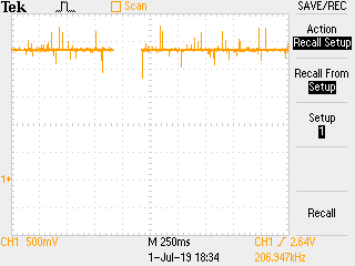
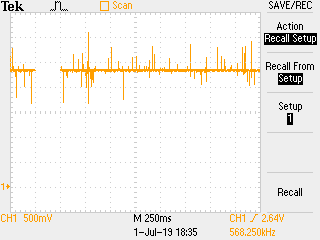
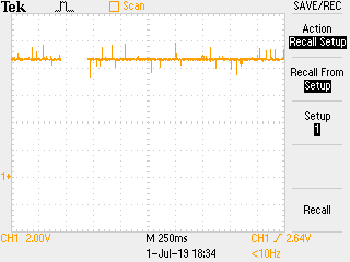
Presently we are simulating the Solar Panel input thru a DC Power Supply Bench with below input.

V In: 21 V DC

I checked the voltage on all pins of the IC. All the voltages indicates as per the datasheet / EVM board details

here are the voltage value of all pins:

Vcc = 20.3 V
MPPSET = 1.65 V
STAT1 = 9 mV (LED On)
TS = 1.92 V
STAT2 = 19.27 V
VREF  = 3.29 V
TERM_EN = 3.29 V
VFB  = 1.16 V 
SRN  = 7.72 V
SRP  = 7.72 V
REGN = 6.02
LODRV = 0.117 V
PH = 7.72 V
HIDRV = 10.71 V
BTST = 11.24 V
All the components and their values was chosen based on the data sheet, evaluation board document and the calculator provided by TI.
I attached the schematic. 
I will appreciate if you could help me to find the problem(s).
Thanks,
  • Hi Nandakumar,

       STAT1 Low and STAT2 High indicate charge is in progress. From the values shown above (mainly VFB) I would expect the charger to charge at precharge current of 200mA, which would be a 4mV voltage drop across your 20milliohm sense resistor. From your SRP SRN values shown above the resolution is not enough to show the voltage drop across the sense resistor. Try connecting your battery through an ammeter to the BAT pin on your board and measure current through that, or use a higher resolution multimeter to measure voltage drop across SRP/SRN.

  • Dear Kedar,

    Thanks for the feedback. I missed to mention the test condition. This is without the battery being connected at the output. Even if the battery is connected, there is no 4mv or 40mV drop across SRP/SRN. Also when Ammeter is connected in series with the battery, there is no charging current observed. It is hardly in the 10mA range.

    However, considering the STAT1 and STAT2 ON / OFF conditions, the datasheets says that both STAT1 and STAT2 should be OFF when Battery is not connected. However, we find that the STAT1 LED is ON even when battery is not connected.

    Please advise.

    Thanks,

    Rajesh

  • Hi Rajesh,

       Can you show the scope capture of SRN, PH and charge current? If battery is not present, we need to analyze the battery absent detection scheme to make sure it is operating correctly. Use a time scale of 200ms.

  • Dear Kedar,

    Please see the waveforms below as per the test conditions.

    1. Without Battery Connected, Input Voltage = 21V DC

    SRN Waveform:


    2.   PH waveform:

    Battery Connected. Below screenshots of SRN, PH and Ammeter screenshot of the Battery connection.

     SRN Waveform:

    PH Waveform:

    c) Charging Current thru Ammeter with Battery Connected

    Also, please note that we have assembled two boards and we have the same issues with both the boards. We have even tried changing the device on one board, but the function does not change.

    Thanks,

    Rajesh

  • Dear Kedar,

    Any possible resolutions for the below issue?

    Thanks,

    Rajesh

  • Hi Rajesh,

       These waveforms don't look like correct operation. PH should be switching from VIN to ground and should be visible in this time scale, even if battery is absent. Your waveform on battery absent shows PH with basically a DC value of ~2.5V even though input source is specified as 21V. The difference in max value of PH is not affected by absence or presence of battery as is shown in the waveform results above. Also SRN shows no oscillation on above waveform as it should during battery absent detection as can be seen in Figure 13. of the datasheet. SRN should be oscillating between maximum charge voltage (set by resistor divider network at VFB) and VLOWV. Please refer to below attachment on how to design schematic and BQ24650 design considerations. I would also direct you to test on BQ24650 Evaluation Module to verify correct operation.

    BQ24650_SchematicChecklist_FINAL.pdf

  • Hi Rajesh,

       Sorry I had already reviewed schematic and found nothing wrong with it. I meant to say layout. You can find BQ24650EVM gerber files here: http://www.ti.com/tool/BQ24650EVM-639 under software link. I would still direct you to a BQ24650 EVM and test on that first. This should help as BQ24650 is evaluated on this EVM and closely mimics your system as you have followed user guide as close as possible.