This thread has been locked.

If you have a related question, please click the "Ask a related question" button in the top right corner. The newly created question will be automatically linked to this question.

TPS56C215: Maximum Cout

Part Number: TPS56C215

Hello,

I have a design with the TPS56C21 these are the main Regulator parameters as recommended by webench power designer:

Vin: 12V,  Vout: 1.0V

Iout: 8Amps

Fsw: 400KHz (selected by me, to decrease IC power)

L: 1u2

Cout:  9 x 47uF (MLCC-

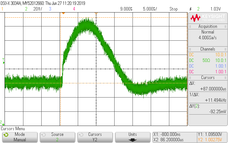
This design drives a FPGA power rail. In the bench test I noticed a large and fast load transient when the FPGA ends the code configuration.The regulator bulk caps are not large enough to absorb this transient before the IC reacts, bringing the 1V0 rail close to 1V1 which is the ABS max of the FPGA.

My believe is the transient is purely due to the lack of bulk capacitance. Changing the SW frequency to 800KHz doesn’t seem to help. Increasing the bulk capacitance from 423uF to 900uF with 9 x 100uF (MLCC – ESR: 2mOhm) reduces the overshoot to 60mV with no noticeable stability issues.

I noticed the 500uF max limit in the TPS56C215 spec sheet. I’d like to be conservative and increase Cout to 600uF (6 x 100uF). My questions are:

  1. How confident can I be there won’t be stability problems with 600uF given it works fine in ONE circuit?
  2. Is there a easy way to determine the stability margin with 600uF? (webench Designer doesn’t allow me to go over 500uF)

Thanks,


JMR


  • Hi,

    The instability mentioned here is multi-pulse issue. It can be understood as, if the output capacitance is too large, one single on-pulse can't charge the Cout to an adequate value, so the following second on-pulse just happened.

    Based on this analysis, I think 600uF should be good to use if you've verified on one board. Doing bode plot with a network analyzer can show the loop stability essentially.

    However, adding output capacitance is not the only way to overcome the high overshoot. Please note that the overshoot comes from energy on the inductor absorbed by the output capacitance. I would suggest you to use 800kHz switching frequency, then you are able to decrease the inductance to, e.g., 0.68uH. Overshoot can be much better even with no extra output capacitance.

    Any further question, please let us know. Thanks!

    Regards,

    Hao

  • Thanks,

    I changed the inductor to 0.56uH and 800KHz. That reduced the overshoot. With this change I'll probably keep the original Cout value.

    Regards,

    Jose Miguel