This thread has been locked.

If you have a related question, please click the "Ask a related question" button in the top right corner. The newly created question will be automatically linked to this question.

TPS65131: Feedback capacitor

Part Number: TPS65131

Hello 

1. feedback capacitor add zero to improve transient response, EQ 11 and EQ 12 in datasheet shows how to select it ,I want to know is there any bad influence if feedback capacitor's value is deviation from calculated value ? if none, available cap range is ?

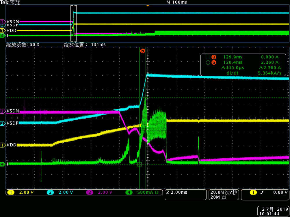
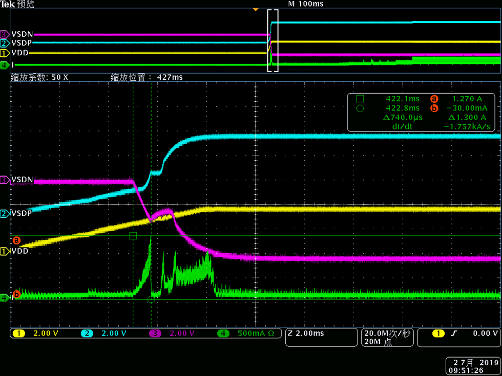
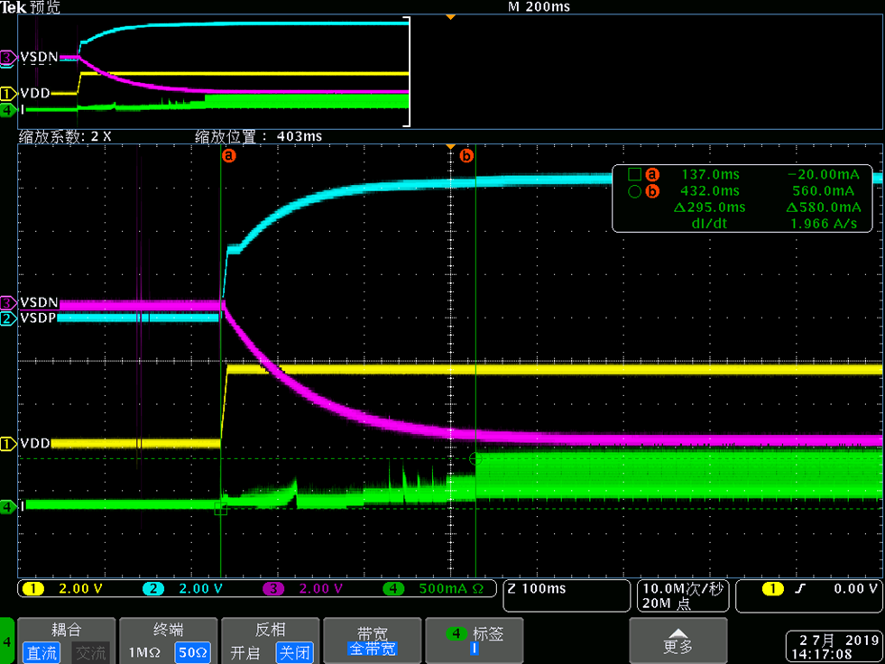
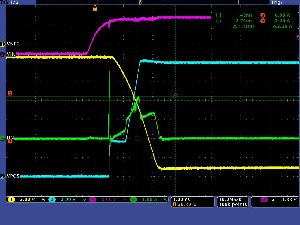
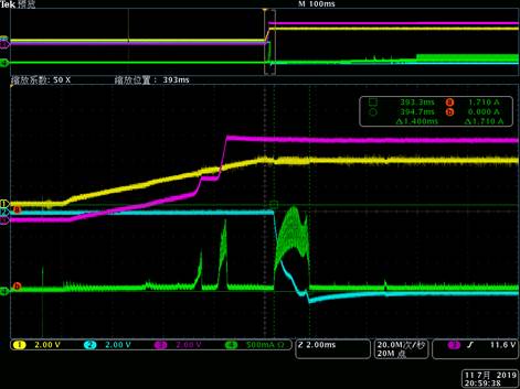
2. My customer use below SCH for Panel application, firstly, the start-up peak input current high up to 2.36A, then he increasing the two feedback capacitor to 1nF,the peak input current decreasing to 1.27A, then he increasing it to 100nF,the peak current decrease to 560mA. wavform is showed below.

1) is this right way to reduce the start-up peak current ? or have any bad influence ? I see one bad influence is that the start-up time change to longer,and I think the dynamic response is also get worse,and I not sure if there are some bad influence for contrl loop.

2) what's the available range of feedback capacitor ?

3) if you have better way to reduce the start-up peak current ? 

  • Hi,

    I have notified our expert regarding this topic. Please expect a response by 7/8/19.

    Thanks,

    Aaron

  • Hello Fandy,

    I would not recommend to deviate too much from the calculated values for feed-forward capacitors for either boost or inverting converter. One other way to reduce the inrush current would be to reduce the value of output capacitors for both boost and inverting converters (typical application in the datasheet shows 22uF) but doing so may also reduce the phase margin of the control loop. So if customer chooses to reduce the output capacitance somewhat, I would suggest to do loop stability measurements to ensure that the control loop still has acceptable phase/gain margin.

    Kind Regards,

    Liaqat

  • Hi Liaqat

    1) How much phase/gain margin for TPS65131EVM or typical SCH in datasheet ?

    2)When feedback cap set to the value calculated through eq11-12, when device start switching,the peak current is high up to 2.36A, the datasheet shows the Ilimit is 1.95A typ, 2.2A max, so it seems TPS65131 current limit protection didn't working ? why ?

  • Hi Fandy,

    1. Phase/gain margin for typical application in the datasheet should be around 50degree/10db.

    2. 2.2A switch current limit is for boost and inverting converter individually and I am guessing that that peak  inrush current is higher because both converters are turning on at the same time. Let me measure the inrush current on an EVM tomorrow and to see what I get.

    Kind Regards,

    Liaqat

  • Hi Fandy,

    I did some measurements on an EVM with +/-12V output on VPOS/VNEG and 3.8V VIN. As I explained in the last post, when both VPOS/VNEG are enabled at the same time, inrush current is higher vs when only one is enabled at a time. That is to be expected since when both converters are enabled at the same time, their respective output capacitors will be charged at the approx. same time. First plot below is with only boost enabled and second plot is with both converters enabled. As you can see, there is soft-start at both converters which somewhat controls the inrush current until rails reach their programmed value. I also measured the switch current and it is well below maximum switch current limit so there is no issue there.

    Kind Regards,

    Liaqat

  • Also, please note that the first big spike in current you see is basically VIN charging the input capacitor before any of the TPS65131 converters start ramping up so you should ignore that first spike.

    Kind Regards,

    Liaqat

  • Hi Liaqat,

    Now My customer add the RC delay to ENN pin, then the start-up peak current is decrease to about 1.8A ,but he want to decrease to1.5A.

    if the phase/gain margin is not enough, could I judge it through  otherthings like waveform since customer havn't network analyzer instrument.

    it seems renew the feedback cap is very efficient for reduce inrush,customer want to additional change feedback cap

  • Hi Fandy,

    You can also get an idea of the loop stability by performing a load step test similar to the scope plots shown below. First plot shows good loop stability and second plot shows poor loop stability.

    Kind Regards,

    Liaqat

    Good loop stability

    Poor loop stability