This thread has been locked.

If you have a related question, please click the "Ask a related question" button in the top right corner. The newly created question will be automatically linked to this question.

TPS7A78: TPS7A78 FB connectivity

Part Number: TPS7A78

Hello,

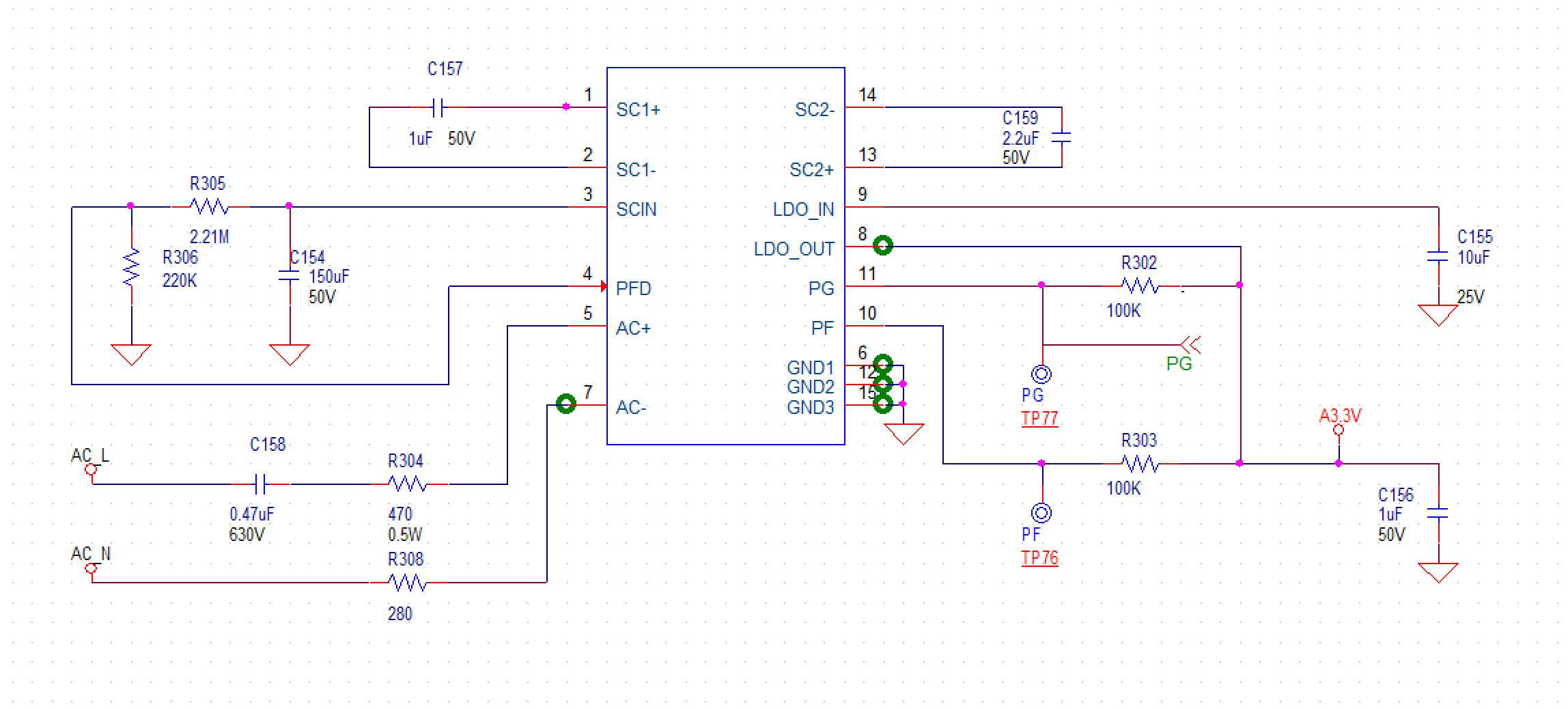
I'm using the TPS7A78 part in FB mode to power digital circuits; in this case GND is not connected to AC-(Neutral) line. The GND line is tracking the AC- line, which could be the hot or neutral line and so far using the demo boards (connecting the TPS7A78 to my digital demo board), I have no issue operating the digital circuits. Should I be concerned that the GND of the digital circuit is tracking the neutral/hot line, in case I swap the polarity of the cable.

I believe that what should matter to the digital circuit is the diff potential, unless there is a leaky active device in the digital circuit. Should I take any precautions, such as adding protective diodes for reverse bias?

Would there be any long term reliability issues?

Thanks.

Sana

  • Hi Sana,

    Can you share a schematic of how you plan to connect the device? Our EVM has precautions to limit the current in FB mode if you accidentally use an earth grounded scope to look at the output. This is not an intended operating mode. In FB mode it is very likely that the device GND is very different from Earth GND.

    Because of the symmetrical nature of AC systems. The device can not see how you connected Line and Neutral. The key requirement is that the cap-drop and surge resistor must both reside in one of the connections.

    We are in the process of updated the datasheet which will make this more clear.

    Regards,

  • Hi John,

    I'm quite careful to not connect any earth ground to the AC line once the part is used in FB mode. Based on the current datasheet, the GND will track the neutral line (first note in page 11 of the datasheet). 

    Here is how I plan to use it. My concern is would a GND (AC like) be an issue for digital circuits, as long as the diff potential is at 3.3V? Are they any precautions that I have to take to protect in case there is an issue on the main line (for added safety and protection)? I cannot use the HB mode because the earth GND is not always available in some of my applications.

    Thanks. Sana

  • Hi Sana,

    Your schematic should work OK as is. The digital loads will only be aware of the A3.3V with respect to the device GND.

    A couple of points to consider:

    1. Your R308 is what we put on our EVM to protect the device in case anyone accidentally connects an earth grounded scope to monitor the load at A3.3V. The pro of keeping it on your system is that it can help to protect your application as well. The con is that it does have a minor impact on efficiency.

    2. There is no MOV or TVS to clamp for surges. If your application needs to survive surge testing, we recommend adding a clamp device making sure that R304 is sized for the maximum DC clamp voltage of whatever is used. This is VMAX_CLAMP/2.5A.


    I hope this answers your question.

  • Hi JCHK,

    Thank you for reviewing the design. With regards to your comments.

    "1. Your R308 is what we put on our EVM to protect the device in case anyone accidentally connects an earth grounded scope to monitor the load at A3.3V. The pro of keeping it on your system is that it can help to protect your application as well. The con is that it does have a minor impact on efficiency."

    For this part, I have simply followed the datasheet recommendation to not connect any of the AC lines directly to the device. (page 3 in datasheet, where it says "Never connect the AC+ or AC- pins directly to the mains." I believe that the 280 would be the typical value. Any recommendations on how to calculate it with regards to efficiency?

    "2. There is no MOV or TVS to clamp for surges. If your application needs to survive surge testing, we recommend adding a clamp device making sure that R304 is sized for the maximum DC clamp voltage of whatever is used. This is VMAX_CLAMP/2.5A."

    I already have the clamp devices right on the main lines (fuse, MOV and choke) but they were not included in this particular schematic page. However, since you mentioned this issue, why did you say 2.5A and what VMAX_CLAMP would be set at, usually? Is it the max VAC? In my case, although the main AC line may be driving as high as 8A (other components), the TPS7A78 will only drive less than 30mA (digital circuitry) and will be set to provide a maximum of 55mA, similarly to the EVM. 

    Thanks. Sana

  • HI Sana,

    For Question #1: Unfortunately there is no simple calculation for predicting efficiency as this part has a long of dynamics. But for resistive power loss you can easily make a prediction by uses the load current you sized for divided by 4 (ILOAD/4) as this would be the current through the AC+/- pins, With that you multiply times the total resistance in the path to estimate the resistive power loss.

    For Question #2: The peak current allowed instantaneously into the TPS7A78 on the AC+/- pins is 2.5A. So if you look at a MOV/TVS spec. As shown below:

    There is a maximum VACRMS rating which should not be exceeded in normal operation. During a surge event, this peak is exceed momentarily while the MOV fires and attempts to shunt the energy. During this time, the MOV may clamp at the Maximum Clamping Voltage highlight above. This is the value to use to determine the minimum surge resistor value. In this example it is 455/2.5 or 182 Ohms

    One last detail I forgot to mention is that our recommended maximum pull-up for the PFD (Power Fail Detect) will be lowered to 200K on the new datasheet. The reason for this is that it help to minimize the possibility of  false alerts. Please scale R305 and R306 accordingly.


  • Hi JCHK,

    Thank you very much for the detailed response. That helps a lot.

    "One last detail I forgot to mention is that our recommended maximum pull-up for the PFD (Power Fail Detect) will be lowered to 200K on the new datasheet. The reason for this is that it help to minimize the possibility of  false alerts. Please scale R305 and R306 accordingly."

    Does that mean that I have to reduce R306 to 200K and calculate R305 based on equations 1 and 2 of datasheet (page 12)?

    PS: I cannot click on "resolved issue" as I still have that question, unless you would like me to open a new case.

    Sana

  • HI Sana,

    Yes. Please re-scale R305 according to equations 1&2.

    If you don't mind clicking resolved on this one. I will jump right on to your next question once submitted.

    Thank you,

  • Hello JCHK,

    Thank you greatly.

    Sana